Fire design, based on the 1993 draft Eurocode 4: Part 1.2, Structural fire design, is introduced in Section 3.3.7, the whole of which is applicable to composite beams, as well as to slabs, except Section 3.3.7.5.
Beams rarely have insulation or integrity functions, and have then to be designed only for the loadbearing function, R. The fire resistance class is normally the same as that of the slab that acts as the top flange of the beam, so only the structural steel section needs further protection. This may be provided by full encasement in concrete of a lightweight fire-resisting material. A more recent method is to encase only the web in concrete. This can be done before the beam is erected (except near end connections), and gives a cross-section of the type shown in Fig.3.31.
In a fire, the exposed bottom flange loses its strength, but the protected web and top flange do not.
For the higher load levels η *(defined in Section 3.3.7.2) and longer periods of fire resistance, minimum areas of longitudinal reinforcement within the encasement, ‘
sA , are specified, in terms
of the cross-sectional area f A of the steel bottom flange. The minimum depth a h and breadth f b of the steel I-section are also specified, for each standard fire resistance period.

The requirements of draft Eurocode 4; Part 1.2 for 60 minutes fire exposure (class R60) are shown in Fig.3.28. The minimum dimensions ha and bf increase with η *, as shown by the three lines in Fig.3.28(a). For other values of η *, interpolation may used.
The minimum ratios f A’ / A are zero for η* = 0.5 (ADE). For η* = 0.7 they are indicated within the regions where they apply. To ensure that the additional reinforcement maintatins its strength for the period of fire exposure, minimum distances 1 a and 2 a are specified, in terms of Lmin b and the fire class. Those for class R60 are show in Fig.3.28(b).
The validity of tabulated data of this type is inevitably limited. The principal conditions for its use, given in the Eurocode, are as follows. The notation is as in Fig.3.15.
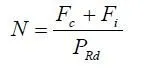
(a) The composite beam must be simply-supported with
![]()
(b) If the slab is composite, the voids formed above the steel beam by trapezoidal profiles must be filled with fire-resistant material.
(c) The web must be encased in normal-density concrete, held in place by stirrups, fabric, or stud connectors that pass through or are welded to the steel web.
The data given in Fig.3.28 are used for the design example in Section 3.11.4. The Eurocode also gives both simple and advanced calculation models, which are often less conservative than the trbulated data, and have wider applicability. These are outside the scope of this volume.