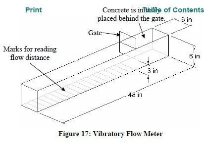
The vibratory flow meter (Szecsy 1997) was developed to measure the flow of concrete under simulated field conditions. The test method is similar to the LCL flow test, Angles flow box, and the vibrating slope apparatus. The test apparatus, shown in Figure 17, consists of a 48 inch long, 6 inch wide, and 6 inch tall box. A vertical gate approximately one-fourth of the length from one end of the box separates the box into two sections. To conduct the test, concrete is placed in the shorter portion of the box. The gate is opened to a height of three inches and a vibrator is inserted into the concrete in the shorter portion of the box. After thirty seconds, the vibrator is removed and the distance the concrete has traveled down the box is recorded.
In testing conducted to compare the results of the vibratory flow meter to rheological parameters, Szecsy (1997) showed that vibratory flow and plastic viscosity exhibited a general relationship; however, the scatter of the data was large. Further, the vibratory flow meter was not always able to detect changes in mixture proportions. For instance, the vibrator flow meter was able to detect changes in sand content for concrete mixtures containing river gravel, but not for mixtures with a crushed limestone aggregate. The vibratory flow meter was able to detect changes in water/cement ratio and high-range water reducing admixture dosage.

Advantages:
The test method is simple and provides a direct result.
The test apparatus consist of readily available equipment and materials.
Disadvantages:
Preliminary test results indicate that the device is not effective in distinguishing between changes in mixture proportions.
The test results are dependent on the type of vibrator used. If an internal poker vibrator is used, the effect of vibration will change as concrete flows further away from the location of the vibrator.
The test results are not given in terms of yield stress or plastic viscosity.
