The width of slab considered in calculations, b, is usually taken as one metre, but for clarity only a width of one wavelength is shown in Fig.3.2. The overall thickness hs is required by Eurocode 4 to be not less than 80 mm; and the thickness of concrete above the main flat surface of the top of the ribs of the sheeting, to be not less than 40 mm. Normally, this thickness is 60 mm or more, to provide sufficient sound or fire insulation, and resistance to concentrated loads.
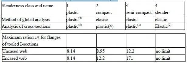
Except where the sheeting is unusually deep, the neutral axis for bending lies in the concrete, where there is full shear connection; but in regions with partial shear connection, there is always a neutral axis within the steel section. Local buckling of compressed sheeting then has to be considered. This is done by using effective widths of flat regions of sheeting. These widths are allowed (in Eurocode 4) to be up to twice the limits given for Class 1 steel web plates in beams, because the concrete prevents the sheeting from buckling upwards, which shortens the wavelength of the buckles.

For sheeting in tension, the width of embossments should be neglected in calculating the effective area, unless tests have shown that a larger area is effective.
For these reasons, the effective area per metre width, Ap, and the height of the centre of area above the bottom of the sheet, e, are usually based on tests. These usually show that ep, the height of the plastic neutral axis of the sheeting, is different from e.
Because local buckling is allowed for in this way, the bending resistance can be calculated by simple theory. There are three situations, as follows.
(1) Neutral axis above the sheeting
The assumed distribution of longitudinal bending stresses is show in Fig. 3.2(b). There must be full shear connection, so that the compressive force in the concrete, Ncf, is equal to the yield force for the steel:

where γap is the partial safety factor for the nominal yield strength fyp of the sheeting. The depth of the stress block in the concrete is given by

For simplicity, and consistency with the method for composite beams, the depth to the neutral axis is assumed to be x, even though this is not in accordance with Eurocode 2. This method is therefore valid when

where MpRd is the design resistance to sagging bending.
(2) Neutral axis within the sheeting, and full shear connection The stress distribution is shown in Fig. 3.2(c). The force Ncf is now less than pa N , and is given by

because compression within ribs is neglected, for simplicity. There is no simple method of calculating x, because of the complex properties of profiled sheeting, so the following approximate method is used. The tensile force in the sheeting is decomposed, as shown in Fig.3.2(d) and (e), into a force at the bottom equal to Nac (the compressive force) and a force Na, where
![]()
The equal and opposite forces Nac provide a resistance moment Mpr equal to the resistance moment for the sheeting, Mpa, reduced by the effect of the axial force Na. It should be noted that in Eurocode 4; Part 1.1, the value of the symbol Ncf depends on the ratio x/hc. It is the lesser of the two value given by equations (3.3) and (3.7). This can be confusing; so for clarity here, a further symbol Npa is introduced. It always has the value

The subscript f in Ncf denotes full shear connection. Where there is partial shear connection, the compressive force in the concrete slab is Nc, which cannot exceed Ncf.
The relationship between Mpr/Mpa and Ncf/Npa depends on the profile, but is typically as shown by the dashed line ABC in Fig,3.3(a). this is approximated in Eurocode 4 by the equation

as shown in Fig.3.2(d) and (e). the lever arm z is found by the approximation shown by line EF in Fig.3.3(b). this is clearly correct when Ncf=Npa, because Nac is then zero, so Mpr is zero. Equation (3.6) with x = hc then gives MpRd. The lever arm is

as given by point F.
To check point E, we assume that Ncf is nearly zero (e.g. if the concrete is very weak), so that Na=0 and Mpr=Mpa. The neutral axis for Mpa alone is at height ep above the bottom of the sheet, and the lever arm for the force Ncf is
![]()
as given by point E. This method has been validated by tests.
The line EF is given by

(3) Partial shear connection
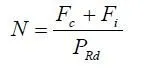
The compressive force in the slab, Nc, is now less than Ncf and is determined by the strength of the shear connection. The depth x of the stress block is given by

There is a second neutral axis within the steel sheeting, and the stress blocks are as shown in Fig.3.2(b), for the slab (with force Nc, not Ncf), and Fig.3.2(c) for the sheeting. The calculation of MpRd is as for method (2), except that Ncf is replaced by Nc, Npa by Ncf, and hc by x, so that: