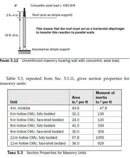
The bearing wall shown in Fig. 5.12 has an unfactored, concentric axial load of 1050 lb/ft. Using hollow concrete masonry units with face-shell bedding, design the wall.
According to the 2009 IBC, and in the context of these example problems (dead load, wind load and roof live load), the following loading combinations must be checked for strength design:
1. 1.2D + 1.6W + f1L + 0.5 (Lr or S or R)
2. 0.9D + 1.6W + 1.6H
The second of these is usually critical, because roof live load must be considered off as well as on.
To apply those loading combinations, let us assume that the total unfactored wall load of 1050 lb/ft represents 700 lb/ft of dead load and 350 lb/ft of live load.

At each horizontal plane through the wall, the following conditions must be met:
Maximum compressive stress from factored axial loads must not exceed the slenderness-dependent values in Eqs. (3-12) or (3-13) as appropriate, reduced by a φ-factor of 0.60.
Maximum compressive stress from factored loads (including a moment magnifiers) must not exceed 0.80 f ² m in the extreme compression fiber, reduced by a φ-factor of 0.60.
Maximum tension stress from factored loads (including a moment magnifier) must not exceed the modulus of rupture in the extreme tension fiber, reduced by the φ-factor of 0.60.
For each condition, the more critical of the two possible loading combinations must be checked. Because there is no wind load, this example will be worked using that the loading combination 1.2D + 1.6L. In theory, we must check various points on the wall. In this problem, however, the wall has only axial load, which increases from top to bottom due to the walls self-weight. Therefore we need to check only at the base of the wall. Try 8-in. nominal units, and a specified compressive strength, fm², of 1500 lb/in.2. This can be satisfied using units with a net-area compressive strength of 1900 lb/in.2, and Type S PCL mortar. Work with a strip with a width of 1 ft (measured along the length of the wall in plan). Stresses are calculated using the critical section, consisting of the bedded area only (2008 MSJC, Sec. 1.9.1.1). At the base of the wall, the factored axial force is
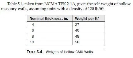
Pu= 1.2 (700 lb) + 1.6 (350 lb) + 1.2 (20 ft × 48 lb/ft) = 2552 lb
To calculate stiffness-related parameters for the wall, we use the average cross section, corresponding to the fully bedded section in the table (2008 MSJC, Sec. 1.9.3).

The maximum permitted compressive stress is
0.60 â‹… 0.80 f ² = 0.60 × 0.80 × 1500 .2 = 720 m lb/in lb/in^2
The maximum compressive stress is much less than this, and the design is satisfactory for this also. Clearly, because this example involves concentric axial loads only, the first criterion (axial capacity reduced by slenderness effects) is more severe than the second (maximum compressive stress from axial loads and bending moments). Because the wall has concentric axial load, there is no net tensile stress, and that criterion does not have to be checked. Because the axial load is concentric, there is no moment, and the magnified moment does not have to be checked. The design is satisfactory. It would probably be possible to achieve a satisfactory design with a smaller nominal wall thickness. To maintain continuity in the example problems that follow, however, the design will stop at this point. Although the 2008 MSJC Code has no explicit minimum eccentricity requirements for walls, the leading coefficient of 0.80 for nominal axial compressive capacity effectively imposes a minimum eccentricity of about 0.1t.
