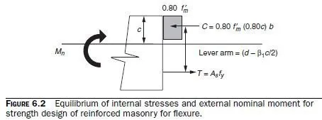
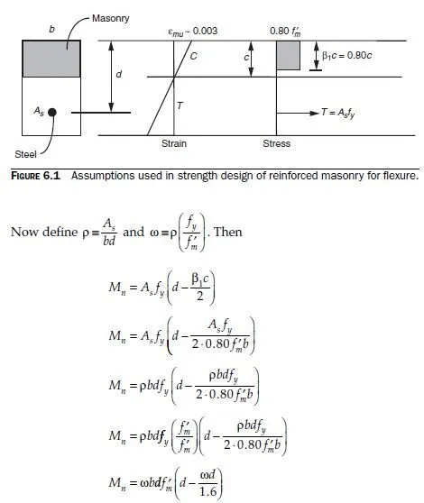
Strength design of reinforced masonry beams follows the same steps used for reinforced concrete beams. The basic assumptions are shown in Fig. 6.1. Strain in the masonry is assumed to have a maximum useful value of 0.0025 for concrete masonry and 0.0035 for clay masonry. Tension reinforcement is assumed to be somewhere on the yield plateau. Because axial load is zero, flexural capacity is equal to either the tension force or the compression force on the cross-section, multiplied by the internal lever arm as shown in Fig. 6.2 (the distance between the tensile and compressive forces).

and finally,
Mn = ωbd2 fm² (1− 0.63ω)
This closed-form expression permits solving for the required dimensions if the steel percentage is known. The variable ω is sometimes referred to as the tensile reinforcement index. For design of masonry beams, where dimensions are known, it is usually easier simply to use

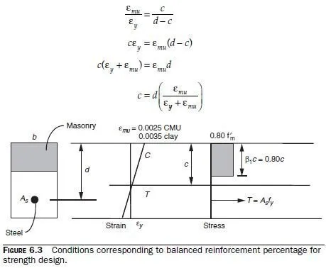
The steel percentage is constrained by the requirement that the steel be on the yield plateau when the masonry reaches its maximum useful strain. For this condition to be satisfied, the steel must yield before the masonry reaches its maximum useful strain. In other words, the steel percentage must be less than the balanced steel percentage, at which the steel yields just as the masonry reaches its maximum useful strain. The balanced steel percentage for strength design can be derived based on the strains in steel and masonry (Fig. 6.3). First, locate the neutral axis under balanced conditions:

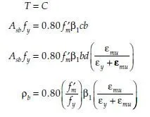
Next, compute the compressive force under those conditions, and compute balanced steel area as the steel area, acting at yield, that is necessary to equilibrate that compressive force:


