The following step-by-step procedure can be used to determine the reactions of plane statically determinate structures subjected to coplanar loads.
1. Draw a free-body diagram (FBD) of the structure.
a. Show the structure under consideration detached from its supports and disconnected from all other bodies to which it may be connected.
b. Show each known force or couple on the FBD by an arrow indicating its direction and sense. Write the magnitude of each known force or couple by its arrow.
c. Show the orientation of the mutually perpendicular xy coordinate system to be used in the analysis. It is usually convenient to orient the x and y axes in the horizontal (positive to the right) and vertical (positive upward) directions, respectively. However, if the dimensions of the structure and/or the lines of action of most of the applied loads are in an inclined direction, selection of the x (or y) axis in that direction may considerably expedite the analysis.
d. At each point where the structure has been detached from a support, show the unknown external reactions being exerted on the structure. The type of reactions that can be exerted by the various supports are given in Fig. 3.3. The reaction forces are represented on the FBD by arrows in the known directions of their lines of action. The reaction couples are represented by curved arrows. The senses of the reactions are not known and can be arbitrarily assumed. However, it is usually convenient to assume the senses of the reaction forces in the positive x and y directions and of reaction couples as counterclockwise. The actual senses of the reactions will be known after their magnitudes have been determined by solving the equations of equilibrium and condition (if any). A positive magnitude for a reaction will imply that the sense initially assumed was correct, whereas a negative value of the magnitude will indicate that the actual sense is opposite to the one assumed on the FBD. Since the magnitudes of the reactions are not yet known, they are denoted by appropriate letter symbols on the FBD. e. To complete the FBD, draw the dimensions of the structure, showing the locations of all the known and unknown external forces.
2. Check for static determinacy. Using the procedure described in Section 3.4, determine whether or not the given structure is statically determinate externally. If the structure is either statically or geometrically unstable or indeterminate externally, end the analysis at this stage.
3. Determine the unknown reactions by applying the equations of equilibrium and condition (if any) to the entire structure. To avoid solving simultaneous equations, write the equilibrium and condition equations so that each equation involves only one unknown. For some internally unstable structures, it may not be possible to write equations containing one unknown each. For such structures, the reactions are determined by solving the equations simultaneously. The analysis of such internally unstable structures can sometimes be expedited and the solution of simultaneous equations avoided by disconnecting the structure into rigid portions and by applying the equations of equilibrium to the individual portions to determine the reactions. In such a case, you must construct the free-body diagrams of the portions of the structure; these diagrams must show, in addition to any applied loads and support reactions, all the internal forces being exerted upon that portion at connections. Remember that the internal forces acting on the adjacent portions of a structure must have the same magnitudes but opposite senses in accordance with Newtons third law.
4. Apply an alternative equilibrium equation that has not been used before to the entire structure to check the computations. This alternative equation should preferably involve all the reactions that were determined in the analysis. You may use a moment equilibrium equation involving a summation of moments about a point that does not lie on lines of action of reaction forces for this purpose. If the analysis has been carried out correctly, then this alternative equilibrium equation must be satisfied.
Computation of Reactions Example
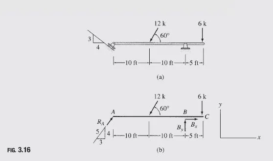
Determine the reactions at the supports for the beam shown in Fig. 3.16(a).
Solution
Free-Body Diagram The free-body diagram of the beam is shown in Fig. 3.16(b). Note that the roller at A exerts reaction RA in the direction perpendicular to the inclined supporting surface.
Static Determinacy The beam is internally stable and is supported by three reactions, RA; Bx, and By, all of which are neither parallel nor concurrent. Therefore, the beam is statically determinate.
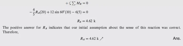
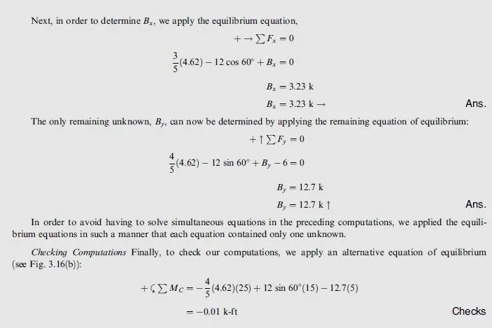
Support Reactions Since two of the three reactions, namely, Bx and By, are concurrent at B, their moments about B are zero. Therefore, the equilibrium equation ∑MB = 0, which involves the summation of moments of all the forces about B, contains only one unknown, RA. Thus,
Example 2
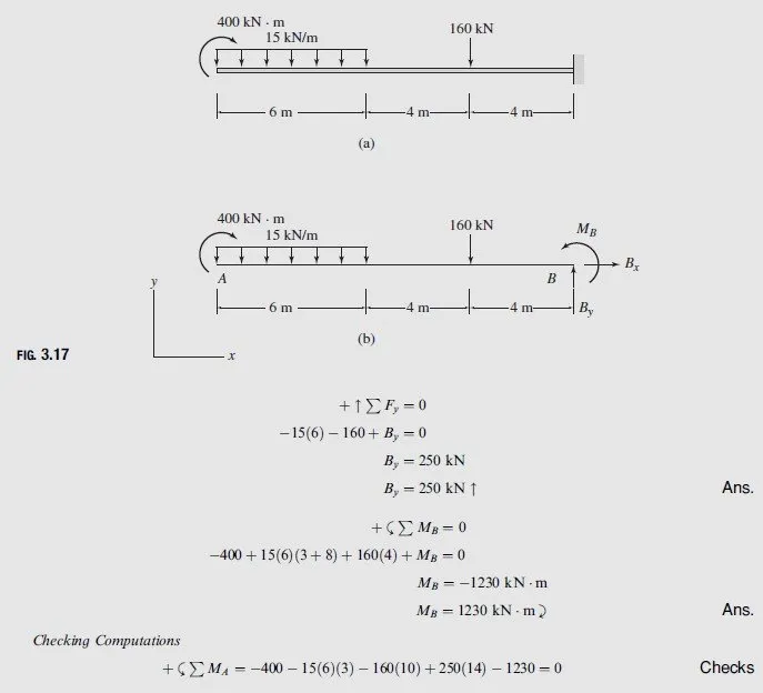
Determine the reactions at the supports for the beam shown in Fig. 3.17(a).
Solution
Free-Body Diagram See Fig. 3.17(b).
Static Determinacy The beam is internally stable with r ¼ 3. Thus, it is statically determinate.
Support Reactions By applying the three equations of equilibrium, we obtain
+ ->∑Fx = 0
Bx = 0
Example 3
Determine the reactions at the support for the frame shown in Fig. 3.18(a).
Solution
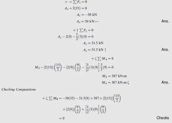
Free-Body Diagram The free-body diagram of the frame is shown in Fig. 3.18(b). Note that the trapezoidal loading distribution has been divided into two simpler, uniform, and triangular, distributions whose areas and centroids are easier to compute.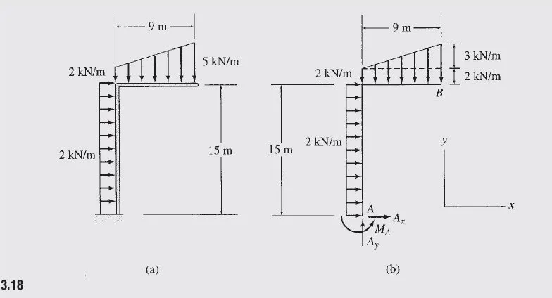
Static Determinacy The frame is internally stable with r = 3. Therefore, it is statically determinate.
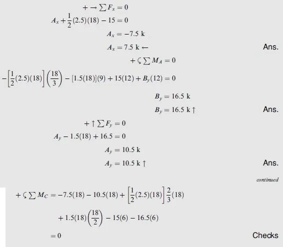
Support Reactions By applying the three equations of equilibrium, we obtain
Example 4
Determine the reactions at the supports for the frame shown in Fig. 3.19(a).
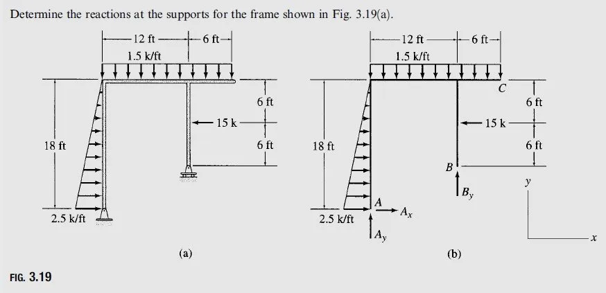
Solution
Free-Body Diagram See Fig. 3.19(b).
Static Determinacy The frame is internally stable with r = 3. Thus, it is statically determinate.
Support Reactions