8.1 Definition of the geoid
The purpose of engineering surveying is to find the relative positions of points in three dimensions; so a 3D co-ordinate system is needed to record the findings. The one absolute direction which can always be found is up, using nothing more sophisticated than a plumb bob. For this reason alone, it makes sense to define one axis of the coordinate system in the upward direction. The other two axes can then be conveniently defined to form an orthogonal set with the first axis and can be thought of as lying at right angles to each other on the surface of a bowl of water held at the foot of the plumb bob. Extended over a hundred metres or so, this water surface is virtually a flat plane1 so a simple Cartesian co-ordinate system, with the z-axis pointing upwards, is ideal for small-scale work. When extended part or all of the way round the world, however, the surface (which is actually a surface of constant gravitational potential energy) is not flat, and up is not always in the same direction so a more elaborate co-ordinate system is needed for larger surveys. There are infinite number of surfaces of constant gravitational potential around the earth, each at a different height. The one used by surveyors worldwide is called the geoid and can be thought of as the surface defined by the sea level around the world, in the absence of wind or tidal effects. The geoid is thus easy to define, but its exact position in any part of the world can be quite hard to find. In Great Britain, a local realisation of the geoid was created by observing the mean tide height at Newlyn in Cornwall between 1915 and 1921 and establishing a physical datum mark at the resulting average point.2 All so-called orthometric heights in Great Britain are measured with respect to this datum. In fact, the shape and position of the geoid is steadily changing, due to effects such as continental drift and global warming. Thus, all countries tend in practice to define their own geoid by measuring heights from a fixed datum close to the geoid, rather than using a common geoid.
8.2 The need for an ellipsoid
The exact shape of the geoid is complex and irregular. It dips in the middle of deep oceans and rises in mountainous areas. Overall, however, it corresponds fairly closely (to within 100 m or so) to a biaxial ellipsoid3 the 3D shape achieved by rotating an ellipse about its minor axis. A useful co-ordinate system for large surveying projects is therefore the so-called Geographical system, in which the positions of points are defined in terms of latitude ( ), longitude (λ) and height (h) above an earth-shaped ellipsoid, as shown for point P in Figure 8.1. Note that:
1 The line PR is the line passing through P which is perpendicular to the surface of the
ellipsoid at the place where it passes through it. It does not, in general, pass through
the centre of the ellipsoid.
2 When the sizes of the ellipsoids major and minor axes (a and b in Figure 8.1) are
known, the geographical co-ordinates of P (Φ , λ, h) can
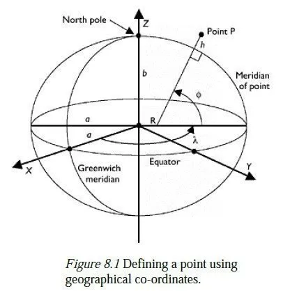
be converted into (x, y, z) co-ordinates in a Cartesian system having its origin at the centre of the ellipsoid, the z-axis lying along the minor axis of the ellipse and the x-axis passing through the zero (Greenwich) meridian. Section 8.4 explains how (and why) this is done.
3 The distance h is called the ellipsoidal height. It is not a height in the true sense, since the geoid is not exactly ellipsoidal in shape.
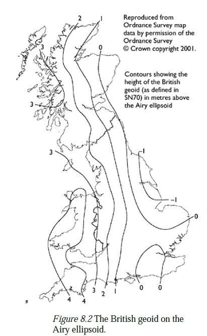
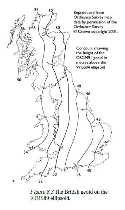
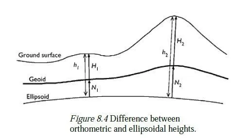
Historically, there was no obvious reason for every country to use the same ellipsoid for mapping purposes so different countries each chose an ellipsoid whose surface corresponded closely to the geoid within their area of interest. These local ellipsoids each have different shapes and different positions and orientations with respect to the earths crust. Moreover, since the position of each ellipsoid is defined in terms of fixed points in the country which adopted it, the relationship between them is continually changing, because of continental drift. In Great Britain, the Airy 1830 ellipsoid was adopted for mapping purposes this corresponds quite closely to the geoid over the British Isles, being about 1 m above it along much of the east coast and about 34 m below it along the west coast see Figure 8.2. By contrast, the separation between the geoid and the ETRS89 ellipsoid varies between 45 and 56 m across Britain, as shown in Figure 8.3. Note that the geoid has been defined in slightly different ways in these two figures but the difference is negligible compared to the difference between the two ellipsoids. The fact that the surface of the geoid is not parallel to any particular ellipsoid gives rise to two effects which need to be considered: 1 If a plumb bob was hung from the point P in Figure 8.1, it would not lie exactly along the line PR. Moreover, the neighbouring surfaces of constant gravitational potential are not even parallel to each other so if the string of the plumb bob was made longer, it might point in yet another direction. These differences, however, are negligible for all practical purposes. 2 More importantly, the difference in ellipsoidal heights between two points on the earths surface will not be the same as the difference in their orthometric heights (i.e. their heights above the geoid or the height difference found by levelling). To convert between the two, it is necessary to know the geoid-ellipsoid separation (usually denoted N, and defined as positive if the geoid lies above the ellipsoid) at each of the two points. In Figure 8.4, it can be seen that the difference in the orthometric heights of two points (H2 H1) is given by:
H2�??H1=(h2−h1)−(N2−N1)
The second of these effects becomes even more noticeable as a result of GPS, which has made it increasingly attractive for countries to use the WGS84 ellipsoid (or a derivative of WGS84, such as ETRS894) in place of their local ellipsoids. Because WGS84 was designed to provide a global best fit with the earths geoid, it is neither as close nor as parallel to the geoid as the local ellipsoid of any particular country. In other words, N is larger, and apt to vary significantly between one place and another, as shown in Figure 8.3.
8.3 Orthometric heights and bench marks
The procedure for determining orthometric heights in Britain, mentioned briefly at the start of Chapter 6, can now be explained in greater detail. During the first half of the twentieth century, a number of fundamental bench marks (FBMs) were established across Britain by precise levelling from the Newlyn Datum. A large number of additional bench marks were subsequently established, using the nearby FBMs as reference heights. To find the orthometric height of any point in the UK, a surveyor would simply level from the nearest BM, as described in Chapter 6. Effectively, the shape of the British geoid was defined by the physical positions and published heights of these bench marks. FBMs consist of elaborately constructed underground chambers in geologically stable places, containing the actual bench mark. These are topped off with a small pillar which protrudes just above the ground and which carries a domed brass marker, whose height is published and upon which a levelling staff can be placed. The top mark is then normally used for levelling but if it is destroyed, it can be rebuilt and its height re-established from the FBM below. By contrast, ordinary BMs are cut into walls of buildings, etc. and are much more liable to subsidence and destruction. The task of regularly checking all BMs throughout the UK and publishing any changes in height was a massive one, and has now been abandoned by the Ordnance Survey because of the advent of GPS. The positions and heights of BMs are still published, but they must now be used with increasing caution, especially in areas liable to subsidence. Instead of defining the British geoid through a network of BMs, the Ordnance Survey now does so by means of a numerical model called OSGM02.5 This was constructed by comparing the orthometric heights of several FBMs around the country (measured as describe above) with their ellipsoidal heights in the ETRS89 system (measured by differential GPS) to give known values for the separation between the British geoid and the ETRS89 ellipsoid at various places around Britain. These values were incorporated into an interpolator which is then able to calculate a value for the geoid-ellipsoid separation at any other place.
1 The British geoid as defined by the new method is slightly different from the ones defined by the old method (e.g. SN70), except at the FBMs used to construct OSGM02.
2 Neither definition yields the exact shape of the true geoid passing through the Newlyn Datum, as both are based on many further measurements and approximations, which potentially contain errors. The inaccuracies inherent in the new definition are, however, small by comparison with the errors inherent in making practical use of it.
This change has been prompted by the fact that an ellipsoidal height can now be found anywhere in the country to within about 1 cm, using differential GPS. One receiver is placed at the point whose height is required; another is placed on a GPS passive station with known ETRS89 co-ordinates, or data are downloaded from a nearby active station. After recording data for about 24 h (necessary because of the comparative inaccuracy of height readings from GPS) the ETRS89 co-ordinates of the new station are computed. The OSGM02 model then provides the orthometric height of the station. To find differences in heights over a short distance, it is more accurate and often quicker to use levelling techniques (fixing one height by GPS if orthometric heights are also required) than to fix both heights independently by GPS. However, the best accuracy which can be expected even from precise levelling is about 2√d mm, where d is the distance between the two points in kilometres so if the two points are more than 25 km apart, it is more accurate (and certainly much quicker) to find their relative heights by means of GPS.