All the theoretical analysis dealt with so far is based on the assumption that the subsoil is isotropic and homogeneous to a considerable depth. In nature, soil is generally non-homogeneous with mixtures of sand, silt and clay in different proportions. In the analysis, an average profile of such soils is normally considered. However, if soils are found in distinct layers of different compositions and strength characteristics, the assumption of homogeneity to such soils is not strictly valid if the failure surface cuts across boundaries of such layers.
The present analysis is limited to a system of two distinct soil layers. For a footing located in the upper layer at a depth D, below the ground level, the failure surfaces at ultimate load may either lie completely in the upper layer or may cross the boundary of the two layers. Further, we may come across the upper layer strong and the lower layer weak or vice versa . In either case, a general analysis for (c – 0) will be presented and will show the same analysis holds true if the soil layers are any one of the categories belonging to sand or clay.
The bearing capacity of a layered system was first analyzed by Button (1953) who considered only saturated clay (0 = 0). Later on Brown and Meyerhof (1969) showed that the analysis of Button leads to unsafe results. Vesic (1975) analyzed the test results of Brown and Meyerhof and others and gave his own solution to the problem.
Vesic considered both the types of soil in each layer, that is clay and (c – 0) soils. However, confirmations of the validity of the analysis of Vesic and others are not available. Meyerhof (1974) analyzed the two layer system consisting of dense sand on soft clay and loose sand on stiff clay and supported his analysis with some model tests. Again Meyerhof and Hanna (1978) advanced the earlier analysis of Meyerhof (1974) to encompass (c – 0) soil and supported their analysis with model tests. The present section deals briefly with the analyses of Meyerhof (1974) and Meyerhof and Hanna (1978).
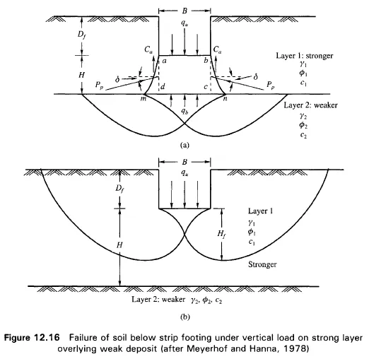
Case 1: A Stronger Layer Overlying a Weaker Deposit
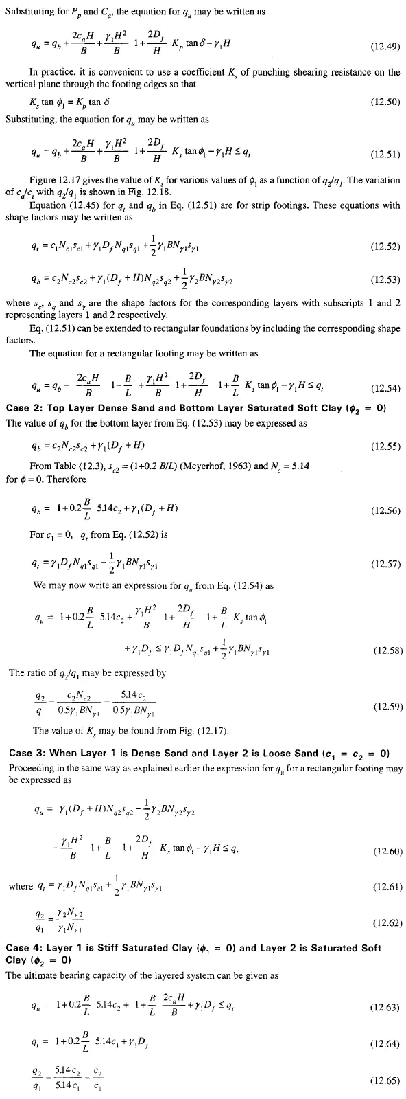
Figure 12.16(a) shows a strip footing of width B resting at a depth D, below ground surface in a strong soil layer (Layer 1). The depth to the boundary of the weak layer (Layer 2) below the base of the footing is H. If this depth H is insufficient to form a full failure plastic zone in Layer 1 under the ultimate load conditions, a part of this ultimate load will be transferred to the boundary level mn. This load will induce a failure condition in the weaker layer (Layer 2). However, if the depth H is relatively large then the failure surface will be completely located in Layer 1 as shown in Fig. 12.16b. The ultimate bearing capacities of strip footings on the surfaces of homogeneous thick beds of Layer 1 and Layer 2 may be expressed as
If q\ is much greater that q2 and if the depth H is insufficient to form a full failure plastic condition in Layer 1, then the failure of the footing may be considered due to pushing of soil within the boundary ad and be through the top layer into the weak layer. The resisting force for punching may be assumed to develop on the faces ad and be passing through the edges of the footing. The forces that act on these surfaces are (per unit length of footing),