Example 4.3
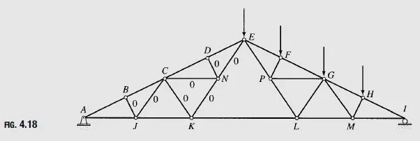
Identify all zero-force members in the Fink roof truss subjected to an unbalanced snow load, as shown in Fig. 4.18.
Solution
It can be seen from the figure that at joint B, three members, AB;BC, and BJ, are connected, of which AB and BC are collinear and BJ is not. Since no external loads are applied at joint B, member BJ is a zero-force member. A similar reasoning can be used for joint D to identify member DN as a zero-force member. Next, we focus our attention on joint J, where four members, AJ; BJ; CJ, and JK, are connected and no external loads are applied. We have already identified BJ as a zero-force member. Of the three remaining members, AJ and JK are collinear; therefore, CJ must be a zero-force member. Similarly, at joint N, member CN is identified as a zero-force member; the same type of arguments can be used for joint C to identify member CK as a zero-force member and for joint K to identify member KN as a zero-force member. Finally, we consider joint N, where four members, CN;DN;EN, and KN, are connected, of which three members, CN;DN, and KN, have already been identified as zero-force members. No external loads are applied at joint N, so the force in the remaining member, EN, must also be zero.
Procedure for Analysis
The following step-by-step procedure can be used for the analysis of statically determinate simple plane trusses by the method of joints.
1. Check the truss for static determinacy, as discussed in the preceding section. If the truss is found to be statically determinate and stable, proceed to step 2. Otherwise, end the analysis at this stage.
(The analysis of statically indeterminate trusses is considered in Part Three of this text.)
2. Identify by inspection any zero-force members of the truss.
3. Determine the slopes of the inclined members (except the zero-force members) of the truss.
4. Draw a free-body diagram of the whole truss, showing all external loads and reactions. Write zeros by the members that have been identified as zero-force members.
5. Examine the free-body diagram of the truss to select a joint that has no more than two unknown forces (which must not be collinear) acting on it. If such a joint is found, then go directly to the next step. Otherwise, determine reactions by applying the three equations of equilibrium and the equations of condition (if any) to the free body of the whole truss; then select a joint with two or fewer unknowns, and go to the next step.
6. a. Draw a free-body diagram of the selected joint, showing tensile forces by arrows pulling away from the joint and compressive forces by arrows pushing into the joint. It is usually convenient to assume the unknown member forces to be tensile.
b. Determine the unknown forces by applying the two equilibrium equations ∑Fx =0 and ∑Fy =0. A positive answer for a member force means that the member is in tension, as initially assumed, whereas a negative answer indicates that the member is in compression. If at least one of the unknown forces acting at the selected joint is in the horizontal or vertical direction, the unknowns can be conveniently determined by satisfying the two equilibrium equations by inspection of the joint on the free-body diagram of the truss.
7. If all the desired member forces and reactions have been determined, then go to the next step. Otherwise, select another joint with no more than two unknowns, and return to step 6.
8. If the reactions were determined in step 5 by using the equations of equilibrium and condition of the whole truss, then apply the remaining joint equilibrium equations that have not been utilized so far to check the calculations. If the reactions were computed by applying the joint equilibrium equations, then use the equilibrium equations of the entire truss to check the calculations. If the analysis has been performed correctly, then these extra equilibrium equations must be satisfied.