Structures are typically too complicated to analyze in their real form. To determine the
response of a structure to external loads, it is convenient to convert the structural system to an idealized form. Stresses and displacements in trusses, for example, are analyzed based on the following assumptions.
Trusses
A truss is a structural system constructed of linear members forming triangular patterns. The members are assumed to be straight and connected to one another by frictionless hinges. All loading is assumed to be concentrated at these connections (joints or panel points). By virtue of these properties, truss members are subject only to axial load. In reality, these conditions may not be satisfied; for example, connections are never frictionless, and hence some moments may develop in adjoining members. In practice, however, assumption of the preceding conditions is reasonable.
If all the members are coplanar, then the system is called a planar truss. Otherwise, the structure is called a space truss. The exterior members of a truss are called chords, and the diagonals are called web members.
Trusses often act as beams. They may be constructed horizontally; examples include roof
trusses and bridge trusses. They also may be constructed vertically; examples include transmission towers and internal lateral bracing systems for buildings or bridge towers and pylons.
Trusses often can be built economically to span several hundred feet.
Roof trusses, in addition to their own weight, support the weight of roof sheathing, roof beams or purlins, wind loads, snow loads, suspended ceilings, and sometimes cranes and other mechanical equipment. Provisions for loads during construction and maintenance often need to be included. All applied loading should be distributed to the truss in such a way that the loads act at the joints. Figure 3.63 shows some common roof trusses.
Bridge trusses are typically constructed in pairs. If the roadway is at the level of the bottom chord, the truss is a through truss. If it is level with the top chord, it is a deck truss. The floor system consists of floor beams, which span in the transverse direction and connect to the truss joints; stringers, which span longitudinally and connect to the floor beams; and a roadway or deck, which is carried by the stringers. With this system, the dead load of the floor system and the bridge live loads it supports, including impact, are distributed to the truss joints. Figure 3.64 shows some common bridge trusses.
Rigid Frames
A rigid frame is a structural system constructed of members that resist bending moment, shear, and axial load and with connections that do not permit changes in the angles between the members under loads. Loading may be either distributed along the length of members, such as gravity loads, or entirely concentrated at the connections, such as wind loads.
If the axial load in a frame member is negligible, the member is commonly referred to as a beam. If moment and shear are negligible and the axial load is compressive, the member

is referred to as a column. Members subjected to moments, shears, and compressive axial forces are typically called beam-columns. (Most vertical members are called columns, although technically they behave as beam-columns.)
If all the members are coplanar, the frame is called a planar frame. Otherwise, it is called a space frame. One plane of a space frame is called a bent. The area spanning between neighboring columns on a specific level is called a bay.
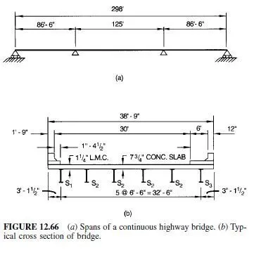
Continuous Beams
A continuous beam is a structural system that carries load over several spans by a series of rigidly connected members that resist bending moment and shear. The loading may be either concentrated or distributed along the lengths of members. The underlying structural system for many bridges is often a set of continuous beams.