The following sequence may serve as a guide to the design of truss bridges:
Select span and general proportions of the bridge, including a tentative cross section.
Design the roadway or deck, including stringers and floorbeams.
Design upper and lower lateral systems.
Design portals and sway frames.
Design posts and hangers that carry little stress or loads that can be computed without a complete stress analysis of the entire truss.
Compute preliminary moments, shears, and stresses in the truss members.
Design the upper-chord members, starting with the most heavily stressed member.
Design the lower-chord members.
Design the web members.

Recalculate the dead load of the truss and compute final moments and stresses in truss members.
Design joints, connections, and details.
Compute dead-load and live-load deflections.
Check secondary stresses in members carrying direct loads and loads due to wind.
Review design for structural integrity, esthetics, erection, and future maintenance and inspection requirements.
Analysis for Vertical Loads
Determination of member forces using conventional analysis based on frictionless joints is often adequate when the following conditions are met:
1. The plane of each truss of a bridge, the planes through the top chords, and the planes through the bottom chords are fully triangulated.
2. The working lines of intersecting truss members meet at a point.
3. Cross frames and other bracing prevent significant distortions of the box shape formed by the planes of the truss described above.
4. Lateral and other bracing members are not cambered; i.e., their lengths are based on the final dead-load position of the truss.
5. Primary members are cambered by making them either short or long by amounts equal to, and opposite in sign to, the axial compression or extension, respectively, resulting from dead-load stress. Camber for trusses can be considered as a correction for dead-load deflection. (If the original design provided excess vertical clearance and the engineers did not object to the sag, then trusses could be constructed without camber. Most people, however, object to sag in bridges.) The cambering of the members results in the truss being out of vertical alignment until all the dead loads are applied to the structure (geometric condition).
When the preceding conditions are met and are rigorously modeled, three-dimensional computer analysis yields about the same dead-load axial forces in the members as the conventional pin-connected analogy and small secondary moments resulting from the self-weight bending of the member. Application of loads other than those constituting the geometric condition, such as live load and wind, will result in sag due to stressing of both primary and secondary members in the truss.
Rigorous three-dimensional analysis has shown that virtually all the bracing members participate in live-load stresses. As a result, total stresses in the primary members are reduced below those calculated by the conventional two-dimensional pin-connected truss analogy.
Since trusses are usually used on relatively long-span structures, the dead-load stress constitutes a very large part of the total stress in many of the truss members. Hence, the savings from use of three-dimensional analysis of the live-load effects will usually be relatively small.
This holds particularly for through trusses where the eccentricity of the live load, and, therefore, forces distributed in the truss by torsion are smaller than for deck trusses.
The largest secondary stresses are those due to moments produced in the members by the resistance of the joints to rotation. Thus, the secondary stresses in a pin-connected truss are theoretically less significant than those in a truss with mechanically fastened or welded joints.
In practice, however, pinned joints always offer frictional resistance to rotation, even when new. If pin-connected joints freeze because of dirt, or rust, secondary stresses might become higher than those in a truss with rigid connections. Three-dimensional analysis will however, quantify secondary stresses, if joints and framing of members are accurately modeled. If the secondary stress exceeds 4 ksi for tension members or 3 ksi for compression members, both the AASHTO SLD and LFD Specifications require that excess be treated as a primary stress.
The AASHTO LRFD Specifications take a different approach including:
A requirement to detail the truss so as to make secondary force effects as small as practical.
A requirement to include the bending caused by member self-weight, as well as moments resulting from eccentricities of joint or working lines.
Relief from including both secondary force effects from joint rotation and floorbeam deflection if the component being designed is more than ten times as long as it is wide in the plane of bending.
When the working lines through the centroids of intersecting members do not intersect at the joint, or where sway frames and portals are eliminated for economic or esthetic purposes, the state of bending in the truss members, as well as the rigidity of the entire system, should be evaluated by a more rigorous analysis than the conventional.
The attachment of floorbeams to truss verticals produces out-of-plane stresses, which should be investigated in highway bridges and must be accounted for in railroad bridges, due to the relatively heavier live load in that type of bridge. An analysis of a frame composed of a floorbeam and all the truss members present in the cross section containing the floor beam is usually adequate to quantify this effect.
Deflection of trusses occurs whenever there are changes in length of the truss members.
These changes may be due to strains resulting from loads on the truss, temperature variations, or fabrication effects or errors. Methods of computing deflections are similar in all three cases. Prior to the introduction of computers, calculation of deflections in trusses was a laborious procedure and was usually determined by energy or virtual work methods or by graphical or semigraphical methods, such as the Williot-Mohr diagram. With the widespread availability of matrix structural analysis packages, the calculation of deflections and analysis of indeterminant trusses are speedily executed.
(See also Arts. 3.30, 3.31, and 3.34 to 3.39).
Analysis for Wind Loads
The areas of trusses exposed to wind normal to their longitudinal axis are computed by multiplying widths of members as seen in elevation by the lengths center to center of intersections.
The overlapping areas at intersections are assumed to provide enough surplus to allow for the added areas of gussets. The AREMA Manual specifies that for railway bridges this truss area be multiplied by the number of trusses, on the assumption that the wind strikes each truss fully (except where the leeward trusses are shielded by the floor system). The AASHTO Specifications require that the area of the trusses and floor as seen in elevation be multiplied by a wind pressure that accounts for 11â„2 times this area being loaded by wind.
The area of the floor should be taken as that seen in elevation, including stringers, deck, railing, and railing pickets.
AREMA specifies that when there is no live load on the structure, the wind pressure
should be taken as at least 50 psf, which is equivalent to a wind velocity of about 125 mph. When live load is on the structure, reduced wind pressures are specified for the trusses plus full wind load on the live load: 30 psf on the bridge, which is equivalent to a 97-mph wind, and 300 lb per lin ft on the live load on one track applied 8 ft above the top of rail.
AASHTO SLD Specifications require a wind pressure on the structure of 75 psf. Total force, lb per lin ft, in the plane of the windward chords should be taken as at least 300 and in the plane of the leeward chords, at least 150. When live load is on the structure, these wind pressures can be reduced 70% and combined with a wind force of 100 lb per lin ft on the live load applied 6 ft above the roadway. The AASHTO LFD Specifications do not expressly address wind loads, so the SLD Specifications pertain by default.
Article 3.8 of the AASHTO LRFD Specifications establish wind loads consistent with the format and presentation currently used in meteorology. Wind pressures are related to a base wind velocity, VB, of 100 mph as common in past specifications. If no better information is available, the wind velocity at 30 ft above the ground, V30, may be taken as equal to the base wind, VB. The height of 30 ft was selected to exclude ground effects in open terrain.
Alternatively, the base wind speed may be taken from Basic Wind Speed Charts available in the literature, or site specific wind surveys may be used to establish V30.
At heights above 30 ft, the design wind velocity, VDZ, mph, on a structure at a height, Z, ft, may be calculated based on characteristic meteorology quantities related to the terrain over which the winds approach as follows. Select the friction velocity, V0, and friction length, Z0, from Table 13.1 Then calculate the velocity from
![]()
If V30 is taken equal to the base wind velocity, VB, then V30 /VB is taken as unity. The correction for structure elevation included in Eq. 13.1, which is based on current meteorological data, replaces the 1â„7 power rule used in the past.
For design, Table 13.2 gives the base pressure, PB, ksf, acting on various structural components for a base wind velocity of 100 mph. The design wind pressure, PD, ksf, for the design wind velocity, VDZ, mph, is calculated from

Additionally, minimum design wind pressures, comparable to those in the AASHTO SLD Specification, are given in the LRFD Specifications.
AASHTO Specifications also require that wind pressure be applied to vehicular live load.
Wind Analysis. Wind analysis is typically carried out with the aid of computers with a space truss and some frame members as a model. It is helpful, and instructive, to employ a simplified, noncomputer method of analysis to compare with the computer solution to expose major modeling errors that are possible with space models. Such a simplified method is presented in the following.
Idealized Wind-Stress Analysis of a through Truss with Inclined End Posts. The wind loads computed as indicated above are applied as concentrated loads at the panel points.
A through truss with parallel chords may be considered as having reactions to the top lateral bracing system only at the main portals. The effect of intermediate sway frames, therefore, is ignored. The analysis is applied to the bracing and to the truss members.
The lateral bracing members in each panel are designed for the maximum shear in the panel resulting from treating the wind load as a moving load; that is, as many panels are loaded as necessary to produce maximum shear in that panel. In design of the top-chord bracing members, the wind load, without live load, usually governs. The span for top-chord bracing is from hip joint to hip joint. For the bottom-chord members, the reduced wind pressure usually governs because of the considerable additional force that usually results from wind on the live load.
For large trusses, wind stress in the trusses should be computed for both the maximum wind pressure without live load and for the reduced wind pressure with live load and full wind on the live load. Because wind on the live load introduces an effect of transfer, as described later, the following discussion is for the more general case of a truss with the reduced wind pressure on the structure and with wind on the live load applied 8 ft above the top of rail, or 6 ft above the deck.

The effect of wind on the trusses may be considered to consist of three additive parts:
Chord stresses in the fully loaded top and bottom lateral trusses.
Horizontal component, which is a uniform force of tension in one truss bottom chord and compression in the other bottom chord, resulting from transfer of the top lateral end reactions down the end portals. This may be taken as the top lateral end reaction times the horizontal distance from the hip joint to the point of contraflexure divided by the spacing between main trusses. It is often conservatively assumed that this point of contraflexure is at the end of span, and, thus, the top lateral end reaction is multiplied by the panel length, divided by the spacing between main trusses. Note that this convenient assumption does not apply to the design of portals themselves.
Transfer stresses created by the moment of wind on the live load and wind on the floor.
This moment is taken about the plane of the bottom lateral system. The wind force on live load and wind force on the floor in a panel length is multiplied by the height of application above the bracing plane and divided by the distance center to center of trusses to arrive at a total vertical panel load. This load is applied downward at each panel point of the leeward truss and upward at each panel point of the windward truss. The resulting stresses in the main vertical trusses are then computed.
The total wind stress in any main truss member is arrived at by adding all three effects:
chord stresses in the lateral systems, horizontal component, and transfer stresses.
 Although this discussion applies to a parallel- chord truss, the same method may be applied with only slight error to a truss with curved top chord by considering the top chord to lie in a horizontal plane between hip joints, as shown in Fig. 13.5. The nature of this error will be described in the following.
Wind Stress Analysis of Curved-Chord Cantilever Truss. The additional effects that should be considered in curved-chord trusses are those of the vertical components of the inclined bracing members. These effects may be illustrated by the behavior of a typical cantilever bridge, several panels of which are shown in Fig. 13.6.
As transverse forces are applied to the curved top lateral system, the transverse shear creates stresses in the top lateral bracing members. The longitudinal and vertical components of these bracing stresses create wind stresses in the top chords and other members of the main trusses. The effects of these numerous components of the lateral members may be determined by the following simple method:
Apply the lateral panel loads to the horizontal projection of the top-chord lateral system and compute all horizontal components of the chord stresses. The stresses in the inclined chords may readily be computed from these horizontal components.

Determine at every point of slope change in the top chord all the vertical forces acting on the point from both bracing diagonals and bracing chords. Compute the truss stresses in the vertical main trusses from those forces.
The final truss stresses are the sum of the two contributions above and also of any transfer stress, and of any horizontal component delivered by the portals to the bottom chords.
Computer Determination of Wind Stresses
For computer analysis, the structural model is a three-dimensional framework composed of all the load-carrying members. Floorbeams are included if they are part of the bracing system or are essential for the stability of the structural model. All wind-load concentrations are applied to the framework at braced points. Because the wind loads on the floor system and on the live load do not lie in a plane of bracing, these loads must be transferred to a plane of bracing. The accompanying vertical required for equilibrium also should be applied to the framework.
Inasmuch as significant wind moments are produced in open-framed portal members of the truss, flexural rigidity of the main-truss members in the portal is essential for stability.
Unless the other framework members are released for moment, the computer analysis will report small moments in most members of the truss.
With cantilever trusses, it is a common practice to analyze the suspended span by itself and then apply the reactions to a second analysis of the anchor and cantilever arms.
Some consideration of the rotational stiffness of piers about their vertical axis is warranted for those piers that support bearings that are fixed against longitudinal translation. Such piers will be subjected to a moment resulting from the longitudinal forces induced by lateral loads.
If the stiffness (or flexibility) of the piers is not taken into account, the sense and magnitude of chord forces may be incorrectly determined.
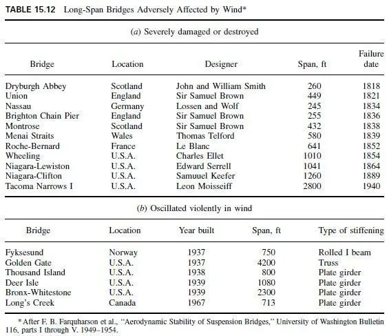
Wind-Induced Vibration of Truss Members
When a steady wind passes by an obstruction, the pressure gradient along the obstruction causes eddies or vortices to form in the wind stream. These occur at stagnation points located on opposite sides of the obstruction. As a vortex grows, it eventually reaches a size that cannot be tolerated by the wind stream and is torn loose and carried along in the wind stream. The vortex at the opposite stagnation point then grows until it is shed. The result is a pattern of essentially equally spaced (for small distances downwind of the obstruction) and alternating vortices called the Vortex Street or von Karman Trail. This vortex street is indicative of a pulsating periodic pressure change applied to the obstruction. The frequency of the vortex shedding and, hence, the frequency of the pulsating pressure, is given by

where V is the wind speed, fps, D is a characteristic dimension, ft, and S is the Strouhal number, the ratio of velocity of vibration of the obstruction to the wind velocity (Table 13.3).
When the obstruction is a member of a truss, self-exciting oscillations of the member in the direction perpendicular to the wind stream may result when the frequency of vortex shedding coincides with a natural frequency of the member. Thus, determination of the torsional frequency and bending frequency in the plane perpendicular to the wind and substitution of those frequencies into Eq. (13.3) leads to an estimate of wind speeds at which resonance may occur. Such vibration has led to fatigue cracking of some truss and arch members, particularly cable hangers and I-shaped members. The preceding proposed use of Eq. (13.3) is oriented toward guiding designers in providing sufficient stiffness to reasonably

preclude vibrations. It does not directly compute the amplitude of vibration and, hence, it does not directly lead to determination of vibratory stresses. Solutions for amplitude are available in the literature. See, for example, M. Paz, Structural Dynamics Theory and Computation, Van Nostrand Reinhold, New York; R. J. Melosh and H. A. Smith, New Formulation for Vibration Analysis, ASCE Journal of Engineering Mechanics, vol. 115, no. 3, March 1989.
C. C. Ulstrup, in Natural Frequencies of Axially Loaded Bridge Members, ASCE Journal of the Structural Division, 1978, proposed the following approximate formula for estimating bending and torsional frequencies for members whose shear center and centroid coincide:

In design of a truss member, the frequency of vortex shedding for the section is set equal to the bending and torsional frequency and the resulting equation is solved for the wind speed V. This is the wind speed at which resonance occurs. The design should be such that V exceeds by a reasonable margin the velocity at which the wind is expected to occur uniformly.