values of the constants for each of the categories. A more detailed description of the exposure categories can be found in the ASCE 7 Standard. The topographic factor, Kzt, takes into account the e¤ect of increase in wind speed due to abrupt changes in topography, such as isolated hills and steep cli¤s. For structures located on or near the tops of such hills, the value of Kzt should be determined using the procedure specified in the ASCE 7 Standard. For other structures, Kzt ¼ 1. The wind directionality factor, Kd , takes into account the reduced probability of maximum winds coming from the direction that is most unfavorable for the structure. This factor is used only when wind loads are applied in combination with other types of loads (such as dead loads, live loads, etc.). For structures subjected to such load combinations, the values of Kd should be obtained from the ASCE 7 Standard. For structures subjected only to wind loads, Kd ¼ 1. The external wind pressures to be used for designing the main framing of structures are given by
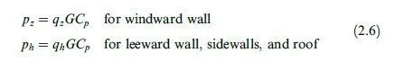
in which h ¼ mean roof height above ground; qh ¼ velocity pressure at height h (evaluated by substituting z ¼ h in Eq. (2.3) or (2.4)); pz ¼ design wind pressure at height z above ground; ph ¼ design wind pressure at mean roof height h; G ¼ gust e¤ect factor; and Cp ¼ external pressure coe°cient.
The gust e¤ect factor, G, is used to consider the loading e¤ect of wind turbulence on the structure. For a rigid structure, whose fundamental frequency is greater than or equal to 1 Hz., G ¼ 0:85. For flexible structures, the value of G should be calculated using the equations given in the ASCE 7 Standard.
The values of the external pressure coe°cients, Cp, based on wind tunnel and full-scale tests, have been provided in the ASCE 7 Standard for various types of structures. Figure 2.5 shows the coe°cients specified for designing the main framing of structures. We can see from this figure that the external wind pressure varies with height on the windward wall of the structure but is uniform on the leeward wall and the sidewalls. Note that the positive pressures act toward the surfaces, whereas the negative pressures, called suctions, act away from the surfaces of the structures.
Once the external wind pressures have been established, they are combined with the internal pressures to obtain the design wind pressures. With the design wind pressures known, we can determine the corresponding design loads on members of the structures by multiplying the pressures by the appropriate tributary areas of the members.
Wind loads Example 2.2
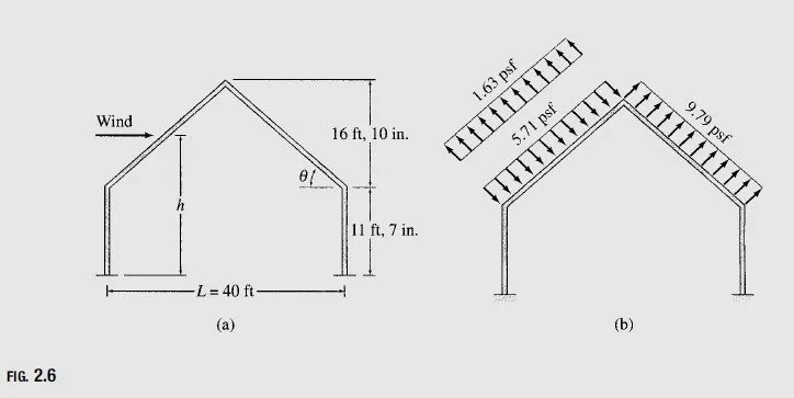
Determine the external wind pressure on the roof of the rigid gabled frame of a nonessential industrial building shown in Fig. 2.6(a). The structure is located in a suburb of Boston, Massachusetts, where the terrain is representative of exposure B. The wind direction is normal to the ridge of the frame as shown.
Solution
Roof Slope and Mean Roof Height From Fig. 2.6(a), we obtain