4.3 The theodolite
The instrument
Angles are measured accurately using a theodolite or total station (which is simply a theodolite that can also measure distances). These are usually classified by the precision to which they can be read; thus, in a one-second instrument an angle reading can be made directly to one second (about 1/200,000 of a radian, i.e. 5 parts per million). Note that this relates only to the resolution of the instrument, not to the accuracy of the angle which has been read. Angles are normally measured in degrees (360 to one complete rotation), minutes (60 to 1 degree) and seconds (60 to one minute). However some instruments measure in gons (400 to one complete rotation) and decimal fractions (0.001 gon=l milligon; 0.0001 gon=l centesimal second). Some newer instruments also measure in radians (2Ï€ radians to one complete rotation) and decimal fractions (e.g. milliradians). This used to be avoided in instruments where the angle was read optically, since there is not a rational number of radians in a full circle, but this is less of a problem with electronic instruments. The following discussion assumes an instrument which works in degrees, minutes and seconds. In construction, the instrument is a telescopic sighting device (described below) mounted on a horizontal axis (the trunnion axis) whose bearings are in turn mounted on a vertical axis. Thus the telescope can be pointed freely in any direction. In particular, the telescope may be rotated through 180° about the trunnion axis without altering any other setting; this is known as transitting. A protractor or circle is mounted on a plane perpendicular to the trunnion axis and to one side of the telescope; when the telescope, viewed from the eyepiece end, has this circle on the users left, it is said to be in the circle-left position; if the telescope is then transitted, it will be in the circle-right position. Most modern theodolites measure the zenith angle; the vertical angle reading is zero when the telescope is sighted vertically upwards, 90° when it is horizontal in the circle-left position, and 270° when horizontal circle right. On electronic theodolites with no obvious circle, circles left and right are often called position I and position II, with the two Roman numerals being engraved onto the body of the instrument. Each motion, horizontal and vertical, has a clamping screw when this is tight (never more than finger-tight), a tangent screw provides a limited range of fine adjustment. The instrument as a whole may be levelled using a spirit level so that the vertical axis is in fact exactly vertical; the horizontal axis is constructed so as to be accurately perpendicular to the vertical axis, though provision is made for adjustment if this becomes necessary. Usually, a theodolite is mounted on a tripod, which allows it to be placed vertically over a known point on the ground; such centring is normally carried out using either a plumb bob, or an optical or laser plummet. Often the instrument is mounted on a tribrach, which in turn is mounted on the tripod. A theodolite telescope is an aiming device with four essential parts:
1 the object-glass, the optical centre1 of which is effectively the foresight of the
telescopes sighting system;
2 the reticle, usually a glass diaphragm, carrying an engraved cross, with a horizontal and
a vertical line, which is set to be on the optical axis of the telescope and which forms
the backsight of the sighting system;
3 the internal focusing lens which is used to focus, in the plane of the reticle, the image of
the target formed by the object-glass;
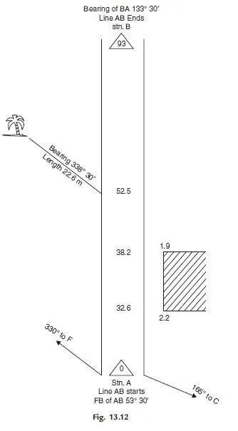
4 the eyepiece to magnify the reticle and the image of the target.The exact form of the reticle lines (often called hairs since on early instruments that is what they were) engraved on the diaphragm varies, but most instruments have a single full-width horizontal line and two shorter horizontal lines, called the stadia lines, one above and one below the full-width line.2 For all vertical readings, the central horizontal line is used. Vertically, some instruments have a single full-depth central line, others a single line on one side of the horizontal line and a pair of lines on the other (see Figure 4.1). A very common error when sighting the telescope vertically is to use one or other stadia line instead of the central full-width line. Always make sure that you can see all the lines engraved on the reticle, when taking a reading. For angle readings, a disk or circle engraved with degrees and minutes is mounted on each axis.3 The horizontal circle may itself be rotated about the vertical axis, so that the value of the reference reading for any angle, or set of angles, may be changed;4 the circle must of course remain undisturbed relative to the axis throughout.
1 A lens acts in the same way as a pinhole, except that it collects more light and has a specific focal
length; the optical centre of the lens can be thought of as the position of the equivalent pinhole.
2 The purpose of these lines is explained in Section 5.3.
3 In conventional theodolites, the circle is made of glass, engraved with legible numbers. In
electronic instruments, the circle is engraved with digital bar code markings, which allow
rotational movements to be detected by a laser.
4 In an electronic instrument, the circle is not actually rotated; however, the horizontal angle
reading can be set to any desired value (including zero) when the instrument is pointing in a given
direction. each set of readings. The vertical circle may also be rotated about its horizontal axis, so that its zero can be set to the vertical. This may either be done manually, with the aid of a special spirit level attached to the circle (called the alidade bubble), or (now more commonly) automatically, using a damped pendulum. In a traditional theodolite, the circles are read optically; the reading system incorporates an optical vernier to enable the desired precision of reading to be obtained. Readings may usually be estimated to a greater precision than provided by the divisions. In a total station or an electronic theodolite, the reading is carried out internally and the limit of precision is determined by the manufacturer.
Handling
Theodolites, whether optical or electronic, are delicate and expensive instruments. They should be handled with great care. Do not jar or knock them, or use the slightest force on them. Do not touch or rub the lenses; if they get wet they can be blotted gently with a tissue. In the field, a theodolite is normally put in its container for every move and not carried on its tripod. If for short moves in steady conditions it is ever carried on its tripod, see that it is secure on the tripod, not too far up on its foot-screws, and that the clamps are all just tight. When carrying the instrument in this way, keep it vertical; it is not designed to resist stresses at any other angle. When being transported in a vehicle, theodolites are vulnerable to high-frequency vibration, which can cause large accelerations even at small amplitude. It is good practice to transport them in a foam surround, or with the container held in the lap of a passenger. Take special care if the instrument has to be set up, even temporarily, on a hard surface. The legs of a tripod are very liable to slip and should be chained together for safety. Never leave an instrument unattended children and animals are very inquisitive. The instrument should be protected from rain and, for precise work, from the sun.
Setting up, centring and levelling
There is no one best way of centring and levelling a tripod. The one described below is simple and works well for centring over a station mark on reasonably level ground. The ability to set up tripods quickly and accurately is of course necessary when working with targets and GPS receivers, as well as theodolites.
1 Position the tripod so that its top is roughly horizontal and above the station mark,
using a plumb bob if desired. Note that the top may be levelled by moving the tripod
feet tangentially, without affecting its position over the mark. On sloping ground, it is
better to have one leg uphill and, if the legs are adjustable, shorter than the others.
2 Attach the instrument to the tripod; if it has a detachable tribrach with optical plummet,
this may conveniently be used on its own for the initial adjustments. The instrument or
tribrach should be set at the centre of the tripod head, with the foot-screws about
halfway along their travel. The optical or laser plummet will now be roughly vertical
and should point within one or two centimetres of the ground mark; if it is more than
about 5 cm from the mark, recheck the orientation of the tripod head and make sure it
is approximately horizontal.
3 If necessary, focus the eyepiece of the optical plummet so that both the reticle and
station mark appear sharp (some optical plummets have separate focussing rings for
these two functions). If your tripod has adjustable legs, tread the feet of the tripod
firmly into the ground.
4 Adjust the levelling screws of the instrument or tribrach until the mark is central in the
field of view of the optical plummet, or, if using a laser plummet, until the ground
mark is illuminated by the laser.
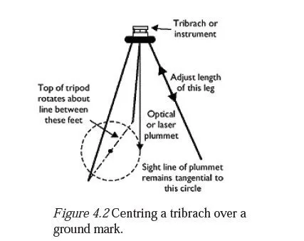
5 Level the bubble on the instrument or tribrach by adjusting the lengths of one tripod leg
followed by another, without moving the feet. As shown in Figure 4.2, this allows the
tribrach to be levelled while hardly altering the point on the ground observed by the
plummet. If the tripod has fixed legs, you can achieve the same effect by moving one
foot at a time radially, as they have not yet been trodden in. You should find that the
plummet is still very nearly pointing at the station mark; if it is not, repeat steps 4 and
5.
6 Fully tighten the leg clamps if the tripod has adjustable legs, or tread in the feet if it has
fixed legs. Make final levelling adjustments to the bubble on the instrument or tribrach
using the levelling screws, then use the tripod centring adjustment to bring the optical
or laser plummet onto the station mark. If the centring adjustment has insufficient
travel, you will have to return to step 4.
7 If the plummet is built into the instrument rather than the tribrach, rotate the instrument
through 360° and watch the position of the sighting point or laser spot on the ground
as you do so. If it moves in a circle, this indicates that its line of sight is not aligned
with the vertical axis of the instrument the effect of this misalignment can be
eliminated by mmoving the instrument on the tripod so that the station lies at the centre
of the circle.
8 For targets, GPS antennae and self-levelling theodolites, the process is now complete. If
manual levelling is necessary, rotate the instrument so that the plate bubble5 (physical
or electronic) lies parallel with the line between two foot-screws. Centre the bubble by
turning these foot-screws equally in opposite directions you will find that the bubble
follows your left thumb. Swing the instrument through 90° and centre the bubble again
by turning the third foot-screw only. Return the instrument to its first position and recentre
the bubble if necessary, repeating until the bubble is centred in both positions.
Swing through 180°, note how much the bubble has moved and bring it halfway back.
Swing through 90° and bring the bubble to the same position with the third foot-screw.
The bubble should now remain in this position (not necessarily central) through
whatever angle the instrument is swung. If it does not, repeat the procedure. Levelling
an instrument really means setting the vertical axis vertical.
9 Check that the instrument is still above the station, and least to an acceptable degree of
accuracy. If it is not, this indicates a bubble error in the spirit bubble used in steps 5
and 6. This can be rectified by moving the instrument on the tripod so that the sighting
point is again over the station and then returning to step 8.
Note that the alignment of an optical or laser plummet which is built into a tribrach
cannot be checked in the manner described in step 7, even though a misalignment may be
present. For this reason, tribrachs must be regularly serviced and should always be
handled with particular care, despite their robust appearance.
Telescope focusing
The ability to focus a telescope correctly and thus eliminate parallax in the readings is possibly the single most important factor in obtaining good readings from a theodolite (including electronic ones) or from a level. A proper understanding of the next two paragraphs is therefore crucial to all surveying. First, with the internal focusing lens right out of focus so that no image of the target is visible, focus the eyepiece so that the reticle is as clear as possible with your eye relaxed. This adjustment depends only on your eyesight and not on the distance to the target; once made, it should only need to be altered if your eye starts to get tired. For each observation, adjust the internal focusing lens so that the image of the target is also sharp. This image should then be in the plane of the reticle, on which the eyepiece is focused. Check this by moving your eye from side to side; there should be no relative movement of the target and the reticle, i.e. no parallax. If there is any, remove it by adjusting the internal focusing lens, not the eyepiece. Having done this, it may seem that the target is no longer exactly in focus; in this case, refocus the eyepiece so that it is, and check that the parallax has disappeared. If it has not, repeat the procedure above, using the internal focusing lens followed (if necessary) by the eyepiece. Note that parallax can be neither eliminated nor introduced by adjusting the eyepiece though it may wrongly appear to be present if the eyepiece is badly adjusted for the observer.
Observing the target
Having eliminated parallax, the cross hairs must be carefully sighted onto the target. Depending on what the target is, it might be easier to bisect it with the single cross hair, or to straddle it with the double cross hairs. If possible, use the same part of the cross hair to sight on each target; this will eliminate any errors due to the cross hairs not being exactly horizontal or vertical. Always use a part of the relevant cross hair (vertical for horizontal angles and vice versa) which is close to the place where the cross hairs meet. It is helpful to be aware of the precision with which a sighting must be made, to achieve a given level of repeatability. If a target is 100 m away, the cross hairs must be sighted onto it with a precision of ±1.5 mm, for a reading which is repeatable to within 5 s. If the instrument and the target are removed and then replaced, it is unlikely that such a level of repeatability could be achieved at all, given the inherent errors of centring over the stations. Repeatability can also be affected by changes in light conditions, particularly if the target has a cylindrical or conical shape. If the sun shines on one side of the target, there is a subconscious tendency to sight the cross hairs onto the sunny side, rather than centrally. This error, known as a phase error, disappears when the target is shaded from the sun.
Reading the angle
In electronic theodolites and total stations, this simply consists of reading the numbers on the display. However, there are still many older instruments in use, with optical reading systems, and this sub-section refers to those instruments. Every pattern of instrument is different in the details of circle reading. Most will have one or more circle-illuminating mirrors, which must be adjusted to obtain even illumination of the circle being observed. Most will have an eyepiece with provision for focusing, through which the circles may be read. In some cases, both circles are visible together, and a single optical vernier applies to both; in other cases, a prism is rotated to select which circle is seen, and separate optical verniers may be used. In each case, rotating the optical vernier causes the scale images to move, by tilting a parallel-sided glass plate in the light path between the circles and the eyepiece. This movement is solely optical and should not be confused with a rotation of the instrument. In higher precision instruments, the reading system automatically takes the mean of the readings on opposite sides of the circle. Every time, before reading the vertical circle, level the alidade bubble; this ensures a consistent circle reading when the telescope is truly horizontal. On many modern instruments, and all electronic ones, this operation is rendered unnecessary by provision of automatic vertical circle indexing, but without that facility it is essential to check the bubble every time when reading vertical angles. Common errors in reading are to read ten minutes or a degree out, to read the horizontal circle instead of the vertical circle or vice versa, to fail to level the alidade bubble before reading the vertical circle or to misread the optical vernier. If you have any doubt on the latter point, it is good practice to turn the vernier to zero and make your best estimate of what the angle reading should be. Then, turn the vernier to take the reading, watching carefully what happens in the main display as you do so. This always provides the clearest possible indication of how the vernier should be read in any particular instrument.