9.4 Grids
Having developed a planar projection from one of the projections described in Section 9.2, it is often convenient to superimpose a right-handed, rectangular Cartesian grid system onto it. This enables the plan position of any point on the map (or ground) to be identified by an (x, y) co-ordinate. The Y-axis is usually defined to lie along a meridian (the central meridian in the case of a transverse Mercator projection), and the x and y coordinates are then known as eastings and northings, respectively.
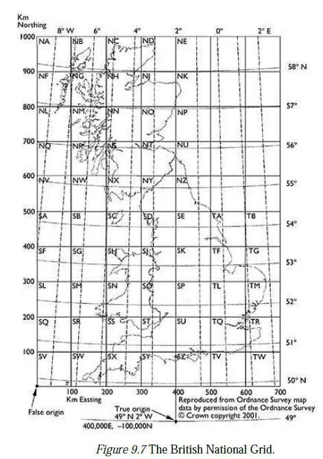
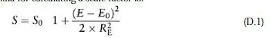
The grid system is positioned by specifying the latitude and longitude of a reference point, which is called the true origin of the system. However, if the true origin is given the co-ordinates (0,0), it may lead to some points having negative co-ordinates, which can be undesirable. The true origin may therefore be given a different set of co-ordinates; these are known as the false co-ordinates of the true origin,9 and the point which thereby acquires the co-ordinates (0,0) is known as the false origin. In the case of the British National Grid, the unit of length is the metre, and the true origin has latitude 49° N and longitude 2° W, with false co-ordinates (400,000E, −100,000N). This places the false origin somewhere to the south-west of the Scilly Isles. All points in the British Isles thus have positive grid co-ordinates, and all points on the mainland can be specified to an accuracy of 1 m using two six-figure co-ordinates. In Britain, this grid is sometimes broken down into 100 km2 with two-letter designators for approximate referencing purposes, as shown in Figure 9.7; thus the coordinates of the Cambridge University Librarys tower (a second-order control point in OSGB36) can be quoted to the nearest centimetre as (544166.76E, 258409.19N), or to the nearest kilometre as TL4458. UTM grids are likewise defined in metres, and the true origin for each zone is where the central meridian crosses the equator. The false co-ordinates of each true origin are (500,000E, 0N) for the northern hemisphere, so that all points in the zone have positive eastings and northings. For the southern hemisphere, the false co-ordinates are usually set to (500,000E, 10,000,000N), so that the northings of these points are positive also. To distinguish points with the same co-ordinates in different UTM zones, the zone number is attached to the easting as a prefix, e.g. the point on the equator with a latitude of 3° W would have UTM co-ordinates of (30,500,000E, 0N). In each case, the grid is attached to the full-size projection, after the central scale factor has been applied. This means that a horizontal distance measured over the surface of the ellipsoid must be multiplied by the local scale factor to convert it to a distance on the grid; likewise, a grid distance must be divided by the scale factor when converting it to a real distance on the ellipsoid. In transverse Mercator projections, the local scale factor is mainly a function of the distance from the central meridian, and therefore depends mostly on the easting10 of a given point, compared to the easting of the central meridian. The exact formula is given in Appendix D; a useful approximation (which assumes a spherical earth) is:
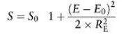
where S is the scale factor at a point whose easting is E, S0 and E0 are the central scale factor and (false) easting of the central meridian, respectively and RE is the mean radius of the earth (which can be taken as 6.381×10⁶ m). For points within 200 km of the central meridian, this formula always gives an answer which is accurate to within 5 parts per million; at 500 km from the central meridian, the accuracy is ±30 parts per million. The formulae required to convert between the geographical (Φ , λ) co-ordinates of a point and its eastings and northings in the British National Grid are fairly complex and are unlikely to be needed by an engineering surveyor. If required, they can be found in Ordnance Survey (1950) or in a document entitled A guide to coordinate systems in Great Britain, available (April 2003) as a .pdf file from the Ordnance Survey website (https://www.ordsvy.gov.uk/). The same site also provides a downloadable Excel® spreadsheet, for performing this and similar calculations.
9.5 Bearings
In surveying, all bearings are measured in a clockwise direction from north, as on a compass. However, north can have different meanings, and so the bearing of a line between two points can have different values, as follows:
1 True bearings are measured with respect to the meridian running through a point. True north is where the meridians all meet, on the ellipsoid in use; note that true north on the Airy ellipsoid (for instance) is not in the same place as true north on the WGS84 ellipsoid.
2 Magnetic bearings are measured with respect to magnetic north, the point on the earths surface which is aligned with its magnetic axis. This point is neither stationary nor coincident with true north on any ellipsoid. The angle between true north and magnetic north is called the magnetic variation, and can be looked up on some types of map (e.g aviation maps). If the magnetic variation is west, then magnetic north is to the west of true north, and the deviation should therefore be subtracted from the magnetic bearing to obtain a true bearing. In Great Britain, magnetic deviation is currently about 4.5° w, and reducing by about 6 minutes annually.
3 Compass bearings (the actual reading from a compass) may differ from magnetic bearings because of nearby ferrous objects, particularly if the compass is mounted in a vehicle. The correction which must be applied to a compass reading to get a magnetic bearing is called the deviation of the compass and is usually plotted as a function of the compass reading. If the deviation is west, then the compass north is to the west of magnetic north, and the deviation should be subtracted from a compass reading to obtain a magnetic bearing.
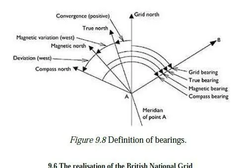
4 Grid bearings are measured with respect to grid north, i.e. the y-axis on the grid system. In the case of a transverse Mercator projection, the y-axis is aligned with the central meridian, so grid north is the same as true north for any point along the central meridian. Elsewhere, the angle between grid north and true north is called the convergence of the meridian and can be calculated as a function of the grid coordinates of the point (Ordnance Survey, 1950:21). Convergence is defined as being positive when true north appears to be to the west of grid north on transverse Mercator projections, it is therefore positive at all points to the east of the central meridian. A positive convergence should be subtracted from a true bearing to obtain a grid bearing. The relationship between these directions and angles is summarised in Figure 9.8, for the bearing from point A to point B. Note that the convergence is shown as being positive, and the variation and deviation are both shown as being west.