3.1 Managing control networks
Before any survey can yield useful results, it is necessary to establish a set of fixed
stations whose positions relative to one another are known usually to a higher accuracy
than will be needed in the final result. A set of such stations is known as a control
network.
If the scope of an engineering project is relatively small (up to 5 km square, say) and
does not have to be tied in with work elsewhere, then it is usually easiest to set up a local
Cartesian co-ordinate system for the work and to use conventional surveying instruments
rather than GPS. Typically, the first control station1 is established at or near the southwest
corner of the site, and defined to be the site origin, having the co-ordinates
(0,0,0).2 A second station is then set up at the north-west corner of the site with its x coordinate
defined to be 0. The horizontal line between the two stations defines the y-axis,
or site north, and the z-axis is defined to be vertically upwards. An orthogonal Cartesian
co-ordinate system is thus fully specified, such that any point on the site has a unique (x,
y, z or easting, northing, height) co-ordinate.
Further control stations will also be needed on the site, and each one is set up by first
choosing a suitable location, then physically establishing the station and finally taking
measurements to find its co-ordinates. The 2D (x, y) position of each station is found by
measuring horizontal angles and/or distances to or from other stations (see Chapters 4
and 5). If needed, the height (z) co-ordinates are usually found separately by levelling, as
explained in Chapter 6.
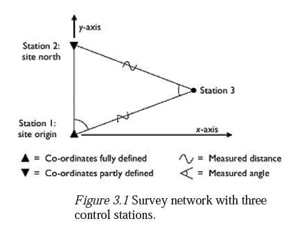
If just one further control station was to be added to the initial two points, there would
be three unknowns in the 2D co-ordinate system: namely the (x, y) co-ordinates of the
third control station and the y co-ordinate of station 2. Finding these unknowns with
redundancy thus requires at least four measurements, of which at least two must be
horizontal distance measurements (if one distance and three angles were measured, there
would be no check that the distance had been measured correctly). A typical scheme of
measurements for fixing a third station is shown in Figure 3.1; here, a horizontal angle
has been measured at station 1, and the instrument has then been moved to station 3
where a second angle and two distances have been measured.
If the final network is to consist of more than three control stations, then a minimum
of 2n−2 readings is required to achieve redundancy in two dimensions, where n is the
total number of stations (i.e. including the origin and site north). In addition, redundancy
considerations require that:
1 there should again be at least two distance measurements;
2 site north (which has one unknown) should be involved in at least two measurements;
and
3 each subsequent point (which will have two unknowns) should be involved in at least
three measurements.
These requirements at least ensure that no gross error will pass unnoticed but it is
generally advisable to take several additional measurements over and above this
minimum, so that any problematic reading can be eliminated from the set altogether,
without loss of redundancy.
The total number of control stations required in the network, and their relative
positions, will depend on the size of the site and the purposes for which they are needed.
If the intention is to set out further points on the ground whose own relative positions
must be guaranteed to be accurate (e.g. the foundation points for a prefabricated bridge)
then there should ideally be three or more control stations near to each point, arranged so
that the positions of the new points will be sufficiently accurate and totally error-poof
when they are set out. If the purpose includes the production of some type of map, then
each relevant feature of the landscape must be visible from (and not too far from) one of
the control stations. Further control stations may also be needed, simply to ensure that the
relative positions of the useful stations are known to a sufficient degree of confidence
and accuracy and also to ensure that the site co-ordinate system will not be lost if one or
both of the original stations were destroyed or displaced.
Many variants exist for establishing a local Cartesian system, as described above. There is no need for site north to be the same as true north, though it reduces the likelihood of mistakes if they are more or less in the same direction. Likewise, the station which defines the site origin does not have to be at the south-east corner of the site but if it is not, then the chances of gross errors are again reduced if its co-ordinates are not (0,0,0) but are defined such that every point on or around the site has positive coordinates. In larger surveys, it is often necessary or more convenient to use an existing regional co-ordinate system or grid. This is typically done by using nearby existing control stations with known co-ordinates, to find the grid co-ordinates of the main control stations around the site. Such grid systems are usually orthogonal, but they often involve a scale factor; this means that one metre in the grid system does not exactly correspond to one metre of horizontal distance on the ground. On a very large survey, this scale factor will alter between one place and another, and this causes discrepancies between angles observed in the field and those measured between the corresponding straight lines drawn on the grid projection see Chapter 9 for further details. There are also complications in using a national datum for height measurements, which are explained in Chapter 8. Since about 1980, the most straightforward way to find the relative positions of stations has been to use differential GPS. GPS receivers are simultaneously placed on two different stations, and their relative positions are known to within about 5 mm after approximately half an hours observation. If national grid co-ordinates are required, one or more national GPS control points (whose grid co-ordinates are now typically published over the Internet) are also included in the scheme of observations. A particular advantage of using differential GPS is that the stations do not need to have a line of sight between them. The use of GPS is explained in Chapter 7. GPS has not, however, completely supplanted the more traditional ways of establishing control networks. It cannot be used if the control stations need to be near tall buildings, beneath trees or in tunnels and the computation required to transform the data into a ground-based co-ordinate system can only be checked by making conventional measurements between some of the control points as well. The equipment is also relatively expensive and is potentially subject to undetectable systematic errors if used on its own; so again, it is reassuring to have an independent method of checking the results it produces. The remainder of this section therefore describes the more traditional ways of establishing control networks.
Triangulation
Until about 1970, all control networks were set up by a process called triangulation. Two stations were established on the ground, and the distance between them (called the base line) was carefully measured.3 The relative position of a third station could then be fixed (with partial redundancy) by measuring all three angles in the triangle between it and the other two stations; no further distance needed to be measured, which was an advantage in the days when distances could only be measured by tape. More stations could subsequently be added to the network by measuring angles between them and two or more of the stations already in the net. For a given instrument accuracy and time budget, the best overall control network for a particular area using triangulation is obtained by distributing control stations as evenly over the area as possible, with well-conditioned4 triangles, and most stations visible5 from at least three others. Since each extra station requires at least three extra observations to fix its horizontal position, the total number of stations is kept as low as possible at this stage; if further control is subsequently required in part of the area, more stations can be established nearby and fixed with reference to the existing stations.6 The advent of electromagnetic distance measurement (EDM) in about 1970 made distance measurement much easier and cheaper, and meant that many of the sides of the triangles in such networks could now be measured as well. This has the effect of making any network much stiffer and eliminates the possibility of an undetected scale error. However, the use of distances to fix the grid positions of stations even in two dimensions requires knowledge of the altitudes of the endpoints, as will be shown in Chapter 11 so the use of distance measurements is sometimes kept to a minimum in conventional surveys, even now.
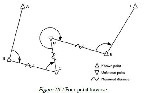
Traversing
When the area to be controlled is long and thin (e.g. a new motorway) or when each station can only see two others, a system of interlocking triangles is impracticable, and a so-called traverse is used instead. In its simplest form, this consists of setting up a total station over a station whose co-ordinates are known, observing another known station, then observing the angle and distance to a station whose position is unknown, but which can now be calculated from the information available. The instrument is now set up over the new station, and the process is repeated for each unknown station in turn, finishing up on a final known station. The agreement between the calculated co-ordinates and the known co-ordinates for this final station is a measure of the accuracy of the traverse, and there are two pieces of redundancy in the set of observations, which can be used to give improved estimates of the positions of all the unknown stations in the traverse. In practice, most control networks are now established by some hybrid of triangulation, traverse and GPS. The key features of a good network are that it should be both stiff and redundant, as described in Chapter 2, and that, if possible, it should be free of any possibility of systematic error.