3.2 Mapping
This book does not attempt to cover mapping to the depth required by cartographers;
however, engineering surveyors will sometimes need to make maps of small areas, so a
few useful guidelines are given here.
1 Decide what scale of map is required before starting. On a 1:1,000 map, a line of width
0.2 mm will represent 0.2 m on the ground, so there is no value in recording the
positions of points to better than this accuracy.
2 For the same reason, there is no value in recording details of shape which are too small
to show up on the map. If a length of fence or hedge does not deviate from a straight
line by more than one lines width when plotted on the map, then only the positions of
the endpoints need be recorded.
3 The purpose(s) of the map will determine what details need to be recorded and how this
should be done. If the map is to be used to plan the positions of new control points,
then the line which records, say, the edge of a ditch should mark the closest point to
the ditch where it would be sensible to establish a control point, rather than the waters
edge. Likewise, the diameter of a trees trunk might be of relevance for determining
lines of sight on the ground, while the size of its canopy will be of relevance for GPS.
4 It is useful to draw a freehand sketch of the intended map before starting to take
measurements. This will help show the amount of detail which can usefully be
recorded and can be marked up with numbers which relate to the points whose
positions are actually measured.
5 If points are to be recorded by means of a total station, it will first be necessary to
establish control points such that every point of interest can be observed from one
control point or another. Also, each control point used for mapping must have a line of
sight to some other known point, which can be used as a reference bearing for the
other measurements. If the control points are only needed for mapping purposes, then
their positions probably do not need to be known to better than decimetre accuracy
but it may be wise to establish them to higher accuracy than this, in case they are
subsequently used for some other purpose.
6 To make a map, the instrument is first sighted on a reference object. Some instruments
can then use the co-ordinates of the instrument position and reference object to orient
themselves and calculate co-ordinates for all subsequent sightings. A staff-holder then
takes a detail pole (with a reflector) to each point of interest, and the bearing and the
distance are recorded by the instrument. Some total stations are motorised and follow
the target automatically; the surveyor with the detail pole can then tell the instrument
when to take the readings, by means of a radio link. This means that the job of
collecting detail can be done by a single surveyor but there have been cases of
motorised total stations being stolen, when the surveyor is too far away to prevent it!
7 Small areas are now often mapped using real time kinematic GPS. The operator walks
from one point of interest to another and records their positions using a GPS receiver
in a small backpack. An electronic map can be produced simultaneously by joining the
points with curves or straight lines and adding symbols or descriptive text, using a
hand-held computer.
As well as making land maps, surveyors sometimes need to map complex shapes such as the façade of a building or the steelwork of a bridge. Devices are now available to do this relatively automatically; essentially these are high-speed, motorised, reflectorless total stations which systematically scan across their field of view and produce a 3D point cloud of observations. These can be fed into solid modelling software, which will clothe the points with a surface to produce a computer model of the object. If several point clouds are captured from different viewpoints and combined, a complete solid model can be produced.
3.3 Setting out
The most common ultimate purpose of an engineering survey is to set out points at predetermined positions on the ground or on partly built structures, to mark where foundation points should be built for a new construction such as a roadway or a prefabricated bridge or the next storey of a building. The full range of setting-out procedures for different engineering purposes is not covered in this book, but is very well and fully described both in Schofield (2001) and in Uren and Price (1994). Instead, this section describes how to set out single points to the highest possible accuracy, and Section 3.5 describes how to assess that accuracy, once the location has been determined.
Setting out in the horizontal plane
If the point is in a suitable place for GPS observations7 and the transformation between the GPS and the local co-ordinate system has been established, then real time kinematic GPS can be used to steer the operator to the desired point, usually to an accuracy of a centimetre or two. Prolonged observation at that provisional point will then determine its position to a higher accuracy, and an appropriate small movement can be made to improve the location of the point. If GPS is not available or appropriate, new points can most easily be set out in the horizontal plane by calculating their bearings and distances from an existing control station whose co-ordinates are known. A total station is set up on the existing station and sighted onto another control station to provide a reference bearing. The angle to be turned through and the distance to be measured8 are calculated by simple geometry see Appendix F for a worked example of these calculations. The instrument is turned through the appropriate angle, and a target is moved until it is on the total stations line of sight and at the appropriate distance, which places it at (or close to) the desired point. Many total stations can perform these calculations automatically, given the co-ordinates of the two control stations and the new point, and will make an audible noise when the target is in the correct place.
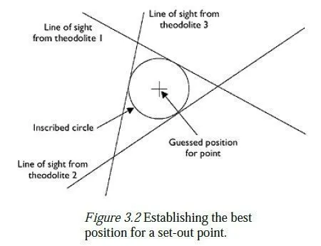
As with control networks, it is essential to have some degree of redundancy when setting out new points, so that any error will be detected before construction work starts. The simplest form of redundancy is to set the point out again, using different control points as reference points; if the two resulting points are reasonably close to each other, the point halfway between them can be used as the best guess for the point to be set out. An alternative method, which avoids the use of distances, involves setting up theodolites over three nearby control points (not necessarily simultaneously) and sighting them along the relevant bearing lines towards the new point, as described above. A small setting-out table is fixed in approximately the correct position, and the lines of sight from the three theodolites are plotted on its surface, to give a figure similar to that shown in Figure 3.2. Generally, the lines will not cross at a point, due to errors in the positions of the three control points, and in setting up the three lines of sight. However, they should very nearly do so the sides of the triangle should not be greater than a centimetre or two. Assuming that the error is likely to be distributed equally between all three lines, the most likely position of the required point is at the centre of the inscribed circle, as shown in the figure-and the radius of the circle gives an indication of the likely accuracy to which the position of the point has been established. The following points are relevant to this method of setting out:
1 Three lines of sight from existing control stations are necessary to guard against the possibility of a gross error, e.g. in calculating one of the bearings. Two lines will always cross at a point if the third one also passes nearby, it is reasonably unlikely that any gross error has occurred.
of the final point will be degraded, as it would be strongly affected by a small
movement of either of the two lines. Note, however, that this does not require the
control stations to be spaced at near −120° intervals round the set-out point, as each
station can be at either end of the line of sight.
3 The reference object should be as far away from the control point as possible, and at
least as far away as the point to be set out. Otherwise, any inaccuracies in the relative
positions of the reference object and the control point will cause a larger inaccuracy in
the setting out.
4 The lines of sight are drawn on the table by first holding a small marker (perhaps a
pencil) on the edge of the table nearest to the theodolite and allowing the observer to
steer it onto the line of sight. This operation is repeated on the far edge of the table,
and the two points are joined by a straight line.
5 For greatest accuracy, each line of sight will actually consist of two lines one from
using the theodolite in its circle left configuration, and one from circle right (see
Section 4.4). The two lines should lie close to one another, if the instrument is well
adjusted, and they should also be parallel, if the marker has been steered carefully by
the observer. A final line is then drawn halfway between the two observed lines and is
taken as the line of sight from that theodolite.
6 It is not necessary to have three theodolites for this task. The table can be positioned
and the first two lines drawn, using two theodolites set up on two of the control
stations. When this has been done, one of them is moved to the third control station,
and the final line is drawn on the table. If only one theodolite is available, the first
line of sight can be approximately recorded using two ranging rods, with a piece of
string tied between them. The theodolite is then moved to the second control station,
and the table is positioned where the second line of sight crosses the taut string. Lines
are now drawn on the table from the second station, and the theodolite is then moved
to the first and third stations for the other lines.
7 If three well-conditioned lines cannot be sighted onto the table, then two lines are
drawn and a suitable target is set up above the intersection. The horizontal distance to
the intersection is then measured from one control station and compared with the
calculated distance. A third straight line can then be drawn on the table perpendicular
to the corresponding line of sight and the appropriate distance from the intersection, to
give a locus of all points on the table which are the correct distance from that control
station. An inscribed circle can then be drawn to touch the three lines, as above.
8 When the most likely position of the point has been established on the setting-out table,
a tripod can be set up over it and an optical or laser plummet sighted down onto the
mark. The table can then be carefully removed, and a more permanent marker
established at the point where the plummet sights onto the ground. (The drawing from
the table should be kept as part of the record of the work.)
9 The size of the triangle gives an indication of the accuracy to which the point has been
set out, but only in relation to the points which were used in the setting out; remember
to add in the inaccuracies of those points, if the absolute accuracy of the set-out point
is required. For an independent check of the work and a better indication of its
accuracy, the point should be resectioned as described in the next section.
Whichever method of setting out is used, it is important to remember that a systematic
error can give an apparently acceptable result which is, in fact, in the wrong place. An error in computing the positions of the local control points could have affected them all equally, and an error in specifying a GPS-to-grid transformation could give incorrect, yet quite consistent, GPS results. For important setting-out points, it is good practice to use as independent a method as possible to check the results. A mixture of GPS and total stations might be used, or, if four points have been set out to form the rectangular base of a building, the lengths of the sides and diagonals could be measured as a simple check. Additionally, the point(s) can be resectioned, as described in the next section preferably, using further control points in addition to those used in the setting out.
Setting out heights
This is a relatively easy process, compared to setting out in the horizontal plane. For greatest accuracy, a temporary bench mark (TBM) is established at the place where the height is to be set out, using the techniques described in Chapter 6. When the height of the TBM is known, a staff or tape can be used to measure up (or down) to the required height. The type of monument used to mark the height depends on the job in hand. It may be a horizontal wooden sight rail for setting out foundations or drainage ditches, or perhaps a stout stake driven into the ground with its top at the specified height, if the surrounding area is to be filled in to that height with topsoil. If the accuracy of the height is critical, it should be checked independently once it has been established, e.g. by levelling to the top of the stake. On building sites, height control is often achieved by means of a precisely horizontal laser beam, which rotates about a vertical axis. This provides a constant height datum across the entire site, by painting a horizontal line on anything placed in its path. A similar technique is used to ensure that steelwork, for instance, is erected vertically; here, the axis of rotation is set to be horizontal, so the rotating laser beam defines an exactly vertical plane. GPS is not generally used for setting out heights accurately, because it is usually slower and less accurate than conventional methods. Usually, a set-out height needs to be accurate only with respect to some nearby datum, and this is much more easily achieved using a level. However, GPS is often used for the real time control of earth-moving machinery, where the accuracy requirements are lower. An antenna mounted on the vehicle can determine its current position and height, and directly control the grading blade according to the height specified on the proposed digital terrain model.