12.2 Scheme of observations
Reciprocal vertical angles can be taken between just two stations, as described above; the number of observations involved is sufficient to ensure that no gross error could pass unnoticed. However, it is strongly recommended that a closed bay of observations is taken, between stations A and B, B and C, then C and A. The vertical closure of this bay will give a good indication of the accuracy of the observations, and if the three stations form an approximately equilateral triangle, their relative heights from RV measurements can be compared with GPS results to verify the quality of the transform parameters used for the latter.
More elaborate schemes of RV observations can also be devised, similar to the schemes for levelling shown in Chapter 6. In addition, RV results can be freely mixed with other levelling results, to provide a fully redundant scheme of vertical control. Generally, though, RV networks would contain fewer observations than levelling networks, simply because of the time needed to make each observation.
12.3 Calculations
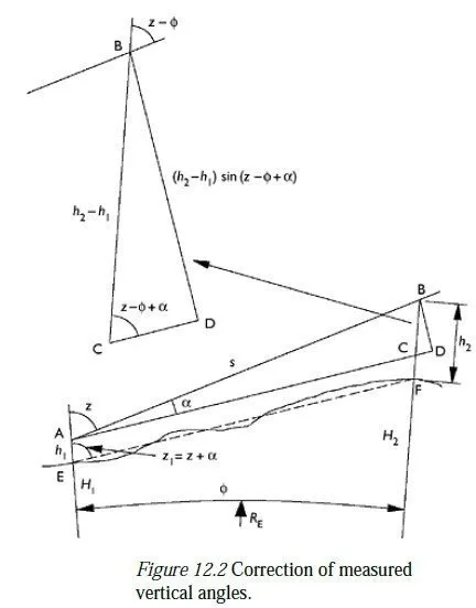
The first stage of the calculation is to find the amount by which the vertical angles measured from each instrument must be altered to allow for the height of the instrument above the local station and the height of the target above the remote station. This correction depends only on the difference between these heights; if the two heights were the same, no correction would need to be made. Note, however, that a different correction must be made for the two sets of observations; each instrument and its nearby target are not generally the same height above their local main station, so the height differences in the two observed rays will not be the same. As shown in Figure 12.2, the correction α which must be added onto each zenith angle measurement is given by the formula:
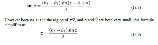
where a is of course in radians. Note that s need not be especially accurate in this equation, since α is small; a simple instrument-to-target distance will be perfectly accurate enough, so the corrections described in Sections 11.3 and 11.4 need not be applied at this stage.
Once the observed zenith angles have been corrected by this amount, the mean slope angle of the line between the two stations can be calculated. Figure 12.3 shows the geometry of the situation between the two stations (E and F), including the fact that the light path between the two stations is not a straight line but tends, in general, to curve above that line
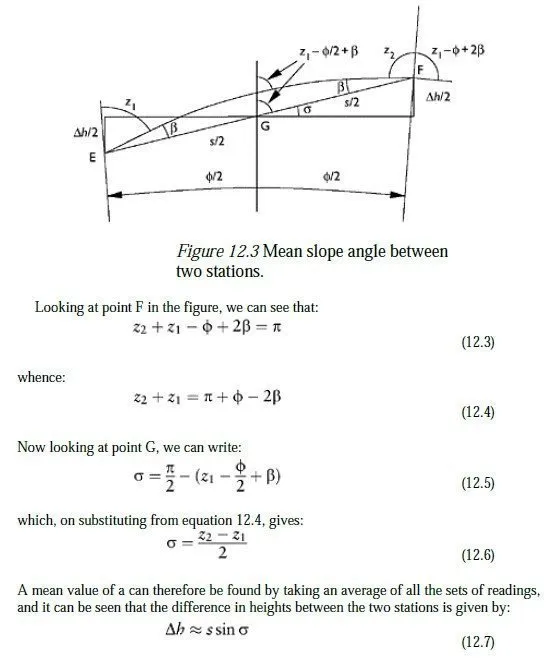
This height difference can be used as shown in Figure 11.7 to allow the accurate calculation of a station-to-station slope distance, and also to allow that slope distance to be converted to a reduced horizontal distance by an adjustment program.
Note that the curvature of the earth and the curvature of the light path have cancelled out in equation 12.6, as a result of measuring the zenith angle at both ends of the ray. It should be borne in mind that this only works if the curvature of the light path is constant,
equation 12.6 will be considerably reduced. Assuming that the light path does have constant curvature, however, we can use the value of β computed from equation 12.4 to estimate a value for the refraction constant defined in equation 11.23. Comparing Figures 11.5 and 12.3, we can see that the angle labelled in Figure 11.5 is equal to z1−Φ +2β in Figure 12.3. So by substituting for in equation 11.20 and then using the approximation of equation 11.1 for dR, we can write:
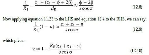
The value for κ obtained from equation 12.10 can be compared with the commonly accepted value of 1/7 for visible light. If visible or infrared laser light has been used to measure the slope distance between the two stations, then this calculated value of κ (which derives from the actual atmospheric conditions at the time of the measurement) should be used in equation 11.26 for the precise adjustment of that slope distance. A worksheet for processing the results of reciprocal vertical angle observations is given in Appendix H. Note that the formulae have been adapted to work with angles recorded in degrees, minutes and seconds, rather than in radians.