7.6 Processing GPS results
The ephemeris information of all GPS satellites, and thus the navigational position of a single GPS receiver, is expressed in terms of a co-ordinate system called WGS84.9 In its basic form, WGS84 is defined as a set of right-handed orthogonal axes, with its origin at the centre of mass of the earth, the x- and y-axes lying in the equatorial plane and the z-axis passing through the North Pole. The exact orientation of the axes was originally set up to coincide with the equatorial plane as defined by the Bureau Internationale de lHeure at the very start of 1984, with the x-axis passing through the prime meridian (approximately the Greenwich meridian) at the same instant. Subsequently, the orientation of the axes has been defined such that the mean drift of all the tectonic plates on the earths surface is zero with respect to them.
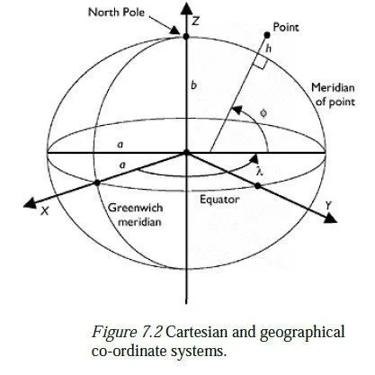
The xyz-axes are complemented with a biaxial ellipsoid10 of defined shape11 (close to the overall shape of the earth), with its centroid at the origin and its axis of rotational symmetry lying along the z-axis, as shown in Figure 7.2. This gives a more natural way of defining a point on the earths surface, in terms of its latitude (the angle ), longitude (the angle λ) and its height above the ellipsoid (h). These two co-ordinate systems are called Cartesian and geographical, respectively, and are explained in more detail in Chapter 9. This is a properly global co-ordinate set for a GPS, but unfortunately it does not suit any single country particularly well, for two principal reasons:
1 The positions of fixed points on the earths surface (e.g. concrete blocks set into the
ground) do not have constant co-ordinates in the WGS84 system, because of
continental drift. In the UK and northern Europe, this drift is in excess of 2 cm per
year; in some parts of the world, it is up to 10 cm per year.
2 The heights reported by GPS measurements are heights above the surface of the
WGS84 ellipsoid, which is in general not parallel to the surface of zero height (the
Geoid see Chapter 8) in any particular country. Thus, the difference in ellipsoidal
heights between two stations measured by differential GPS might be quite different
from the difference in their orthometric heights, as measured using a level. A naïve
surveyor might be surprised to find that water can flow from a point with a low
WGS84 height to another point with a greater WGS84 height!
To make proper use of GPS results, it is therefore necessary to understand about the relationship between WGS84 and heighting and mapping co-ordinate systems used within a particular country. In Europe, the first step was to take the accepted WGS84 co-ordinates of a number of ground stations around Europe (all on the Eurasian tectonic plate) in 1989, and to establish a co-ordinate system or frame similar to WGS84 which is defined to be the best fit to those published co-ordinate values. This co-ordinate frame is called ETRF89,12 and effectively eliminates the first of the two problems described above, by slowly drifting away from WGS84. The ETRF89 co-ordinates of all immovable ground stations in the UK remain constant, and the definitive ETRF89 co-ordinates of several GPS control points around the UK are published by the Ordnance Survey. By setting up a base station on one or more of these control points and using differential GPS, the precise ETRF89 co-ordinates of any other point can be found.13 ETRF89 is simply a framework of points which form the practical realisation of a larger system called ETRS89. This system defines that the WGS84 ellipsoid should be used to convert ETRS89 Cartesian co-ordinates (x, y, z) to geographical co-ordinates (λ, ). Amongst other things, it also predicts the rate at which the ground stations are moving with respect to the WGS84 system, and thus provides a method for defining other ETRFs in the future.
For surveying work, it is usually necessary to transform the ETRS89 co-ordinates (geographical or Cartesian) into suitable local mapping co-ordinates. There are two principal types of transform which can be set up to do this:
1 The one-steptransform If the transform is only to be used over a small area of land (up to 10 km square, say) a localised transform can be set up by quoting the 3D positions of three or more14 points in the local co-ordinate system (i.e. easting, northing and height in the countrys mapping system, or a site co-ordinate system) and also in ETRS89. Provided the points are well distributed over the area in which the transformation is to be used,15 the errors inherent in this type of transform are small by comparison with the errors inherent in differential GPS. All other points whose positions have been found with respect to ETRS89 can then be processed through the transform to find their local co-ordinates.
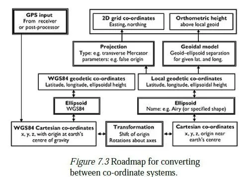
2 The classical transform In all mapping projection systems there is a scale factor, which varies from place to place, by which a distance measured on the ellipsoid must be multiplied before it can be plotted on the projection (see Chapter 9). The one-step transform can accommodate this, but assumes that the scale factor is constant over the area for which the calculated transformation is to be used. If the area is too big for this assumption to be valid, it is necessary to use the so-called classical or Helmert transform, which first transforms the ETRS89 (x, y, z) co-ordinates into equivalent (x, y, z) co-ordinates of whatever ellipsoid has been used for the mapping projection (Airy, in the UK). These are then converted to geographical co-ordinates (latitude and longitude) for the relevant ellipsoid (see Chapter 8), and appropriate projection system is applied to give map co-ordinates of easting, northing and height above the local ellipsoid (see Chapter 9). Then, data must be available to convert the height above the local ellipsoid into a height above the geoid (also known as an orthometric height). A complete roadmap of this process is shown in Figure 7.3. As with the one-step transform, a classical transform can be established if the coordinates of three or more points are known, both in the ETRS89 system and also in one of the local systems. A classical transform will produce valid results over a much larger area than a one-step transform. In order to set it up, however, it is necessary to know the coordinates of three or more points in both systems, i.e. in WGS84 (or a realisation of WGS84 such as ETRS89), and also with respect to the ellipsoid used for the local mapping projection system. If the map co-ordinates and projection method are known, the latitude and longitude on the local ellipsoid can easily be calculated; but to find the ellipsoidal heights from the orthometric heights, the separation between the geoid and the local ellipsoid must be known at each point. Likewise, to obtain orthometric heights from GPS data using a classical transform, it is necessary to have a method for converting a height above the local ellipsoid to an orthometric height at any point within the area of interest.
Both transforms allow for full 3D rotation and translation, to convert from one co-ordinate system to the other. In addition, they both make provision for a scale factor to be introduced, to give the best possible fit between the two systems. This can be useful, but the scale factor must then be applied to any distance which is to be converted from a real distance to one in the local coordinate system, or vice versa. In the case of the classical transform, this scale factor is additional to any scale factor implied by the projection method; so when setting up classical transforms, it is often better to insist that the transformational scale factor is kept at unity. It is clear from the descriptions above that the one-step transform is the easier one to use, provided the area of application is sufficiently small. Exact details of how to set up and apply both these types of transform will be found in the user manual for the postprocessing software provided by the GPS supplier.
7.7 Further details of GPS
The present GPS system consists of three so-called segments:
1 The control segment This comprises the computing power necessary to track the
satellites and to predict their orbits ahead for 24 h using a highly sophisticated model
of the earths gravitational field. Tracking is done by a network of six tracking stations
around the world, which then feed information back to the main control centre in
Colorado. The orbital predictions are uploaded to the satellites every 24 h.
2 The space segment This comprises the 24 satellites, each of which receives and stores
its predicted orbit, and transmits this and other information to¦
3 The user segment The rest of the GPS community.
Despite the huge expense of deploying and maintaining the satellite network, an expense borne by the US Department of Defense, the US Government is currently committed to maintaining a level of free civilian access to the system.
The GPS signal
Each of the satellites transmits signals on two carrier frequencies, both derived from a fundamental oscillator running at 10.23 MHz. The two frequencies are L1, 1,575.42 MHz or 154 times the fundamental and L2, 1,227.60 MHz or 120 times the fundamental. As explained earlier, the purpose of having two frequencies is to enable the correction of errors caused by ionospheric effeThese codes are:cts. Each satellite also transmits a number of digital signals modulated on the L1 and the L2 signals. It is important to realise that since the signal strength is so weak in relation to the background noise and all the satellites transmit at the same frequencies, a particular transmission can only be recognised by knowing in advance what code is modulated onto it, and thus what to listen for.16 These codes are:
1 The coarse acquisition or C/A code, a pseudorandom17 bit sequence of length 1,023 bits, different for each satellite and with a repetition time of 1 ms. The C/A code enables the receiver to distinguish between transmissions from the different satellites. It is used in low-cost navigation receivers as the basis for measurements. The bits are released at a rate of 1.023 Mb/s (the so-called chipping rate, derived from the fundamental oscillator), so one bit corresponds to a distance of approximately 300 m. The C/A code hence gives access to what is known as the standard positioning service.
2 The precision or P-code, also a pseudorandom bit sequence, but at ten times the frequency of the C/A code, with a chipping rate of 10.23 Mb/s. The cycle length of the complete P-code is in excess of 37 weeks, and each of the satellites is allocated a different week, so that each satellite effectively has its own P-code. The code for all satellites is reset every week at midnight on saturday/sunday. Contrary to what is said in much of the early literature, the P-code is not restricted to military use in itself. The generation algorithm is, and always was, in the public domain. However, its use can sometimes be denied to the civilian user by the substitution of an encrypted form of Pcode known as the Y-code. The encryption algorithm is not publicly available. Encryption is known as anti-spoofing or AS, since its purpose is to prevent an enemy force from setting up a spoof transmitter which could make the US military receivers indicate false positions.
3 The navigation message, a digital data stream running at 50 b/s. This message contains, amongst other things, orbital information (called the ephemeris) for the transmitting satellite, repeated every 30 s, and less precise almanac information to tell the receiver which other satellites are likely to be visible. Reception of the almanac for the whole constellation takes 12.5 min.
The navigation message and the P- or Y-code are carried on both L1 and L2 frequencies, whereas normally the C/A code only appears on L1. This makes acquisition of L2 signals difficult when AS is present, but the manufacturers of survey receivers have developed ingenious ways of avoiding the problem.
Ionospheric effects As mentioned earlier, these can be estimated by comparison of pseudoranges measured on both L1 and L2 frequencies. (It should be noted that the ionosphere delays the code parts of the signals, but advances the carrier phase by an equal amount.) Single frequency receivers thus have greater difficulty in resolving phase ambiguities, since they have no estimate of the ionospheric effect, that being derived from the different delays in the code transmissions on the two frequencies.
GPS time The fundamental measure of time used in the world is called universal co-ordinated time (UTC). The length of a UTC second is defined by the decay rate of caesium. To ensure that midnight continues to occur in the middle of the night on average, leap seconds are occasionally introduced into UTC, so that the final minute in a year often lasts for 61 s instead of 60 s.18 GPS time is measured in weeks and seconds from 0:00:00, on 6 January 1980. It is established by averaging the clock readings from all the satellites19 and from a groundbased master clock, and is then steered so that its seconds increment within one microsecond of UTC seconds. However, GPS time has no leap seconds, so now runs ahead of UTC by more than 12 s. A further complication is that the week counter is only 10 bits long, so rolls over to zero after 1,023 weeks. This occurred for the first time in August 1999, causing problems in many receivers. It will happen again in March 2019.
7.8 Other satellite positioning systems
GPS has never been the only satellite positioning system; other systems such as Transit preceded it, and Russia has a system called Glonass, which has remained mainly a military system. To enhance the accuracy of GPS in certain areas and to provide a backup system in the event of GPS failing or being withdrawn, several countries have already developed regional augmentation to the GPS (and Glonass) signals, using geostationary satellites.
These include WAAS in the United States, MS AS in Japan and EGNOS (European Geostationary Navigation Overlay System) in Europe. EGNOS is due to come online in 2004 and will deliver positional accuracy of better than 5 m from a single receiver, throughout Europe. In addition, the European Union has planned an entirely independent satellite system called Galileo, which will further enhance navigational accuracy as well as provide a number of other services (e.g. for search and rescue). In particular, it is intended that there should be no common mode of failure between GPS and Galileo. Galileo is planned to come online in 2008 and will consist of 30 satellites in circular orbits inclined at 56° to the equator; there will be three orbital planes, with ten satellites equally spaced on each plane. The orbital radius will be 30 Mm, giving an orbital period of about 14 h. Galileo is conceptually quite similar to GPS and will also work by measuring the time taken for signals to travel from a satellite to a receiver. However, it will broadcast signals on three different frequency bands (1,1641,215 MHz, 1,2601,300 MHz and 1,5591,591 MHz) which should significantly improve the calculation of atmospheric delays. In addition, some of the signals will incorporate an integrity check, intended to guard against false indications of position. Galileo will bring two major benefits to the surveying community: 1 It will improve accuracy and reduce observation times by providing more satellites; GDOPs of greater than 6 will cease to occur. 2 It should perform noticeably better than GPS in built-up areas, due to the integrity checks in the signals. On the other hand, Galileo is planned as a commercial venture, in which the users will pay for the deployment and maintenance of the system. In particular, it is intended that commercial users (i.e. surveyors) should pay for the enhanced positioning services that they will need, by means of access-protection keys on their receivers.